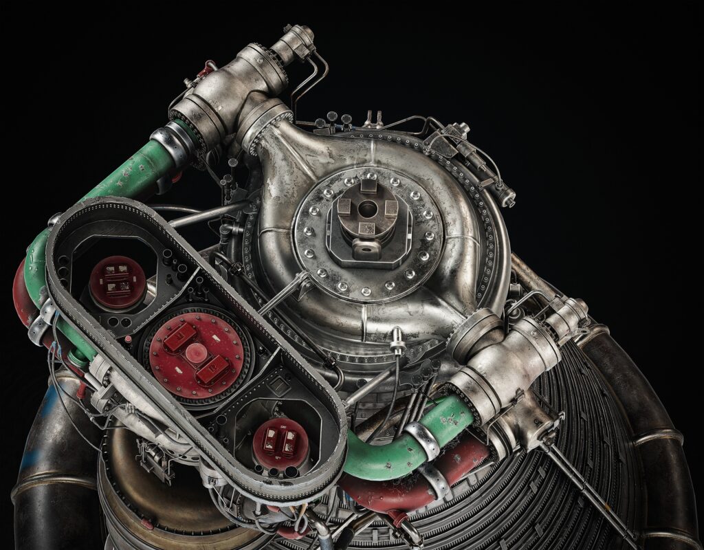
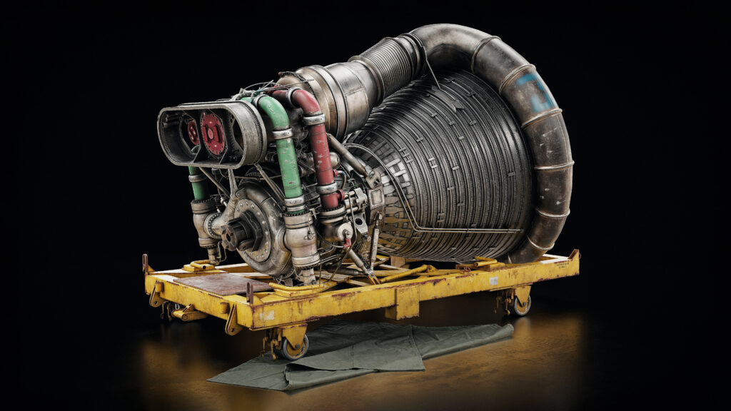
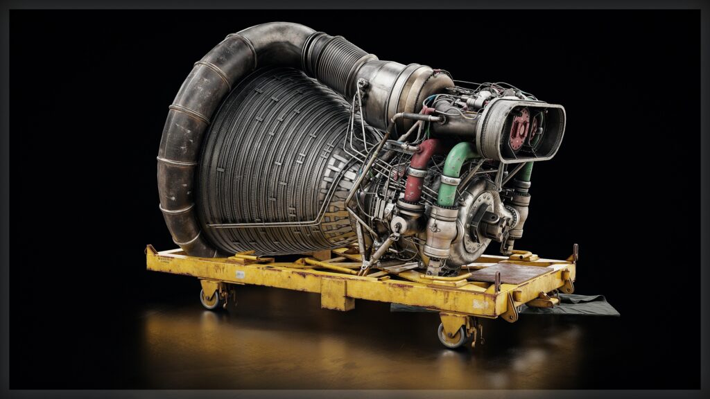
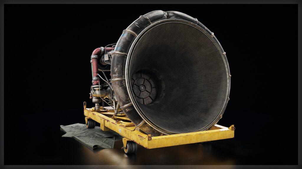
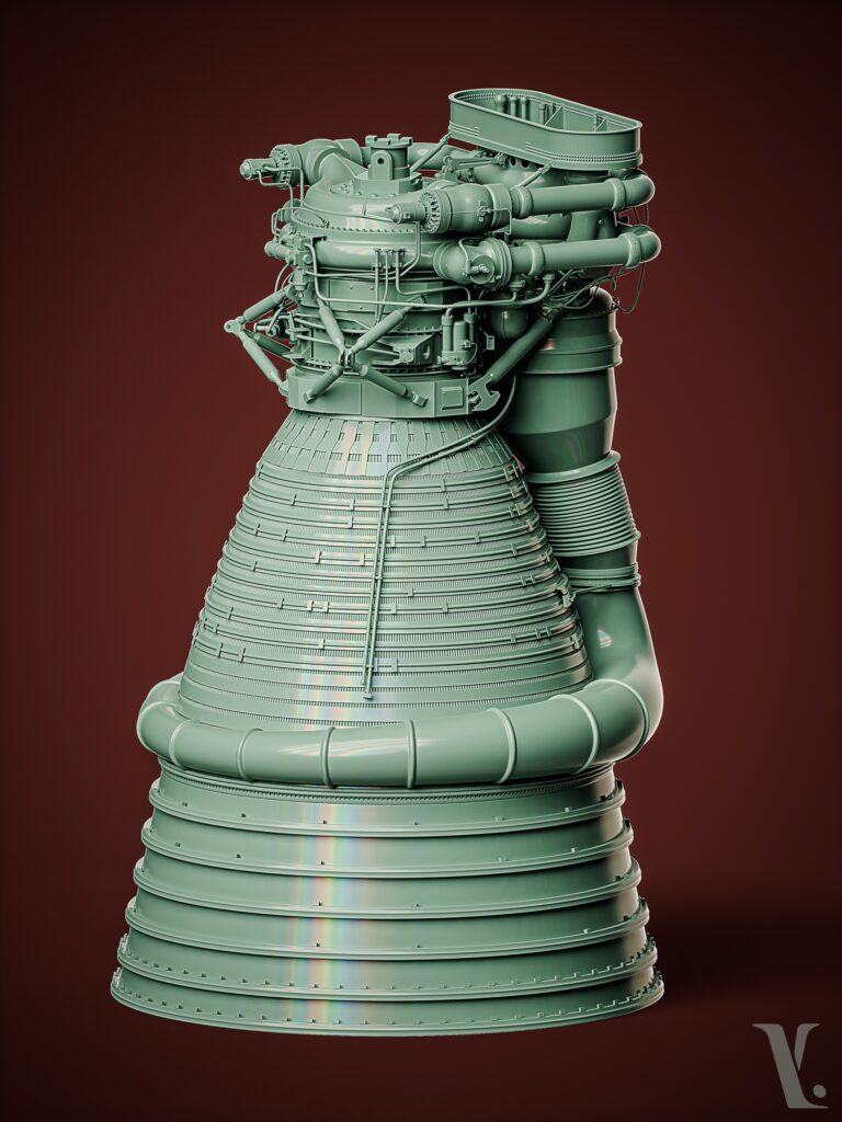
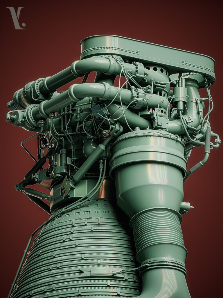
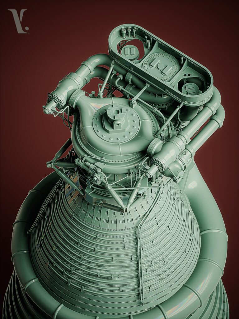
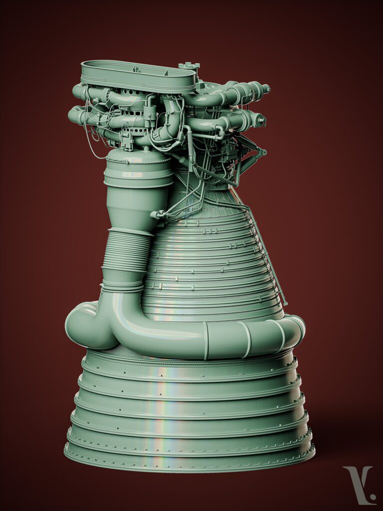
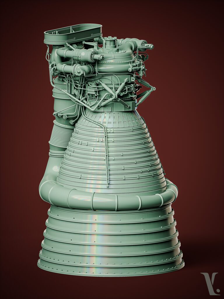
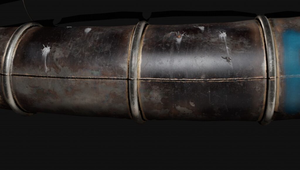
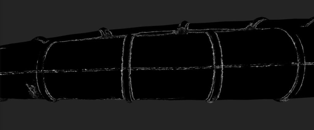
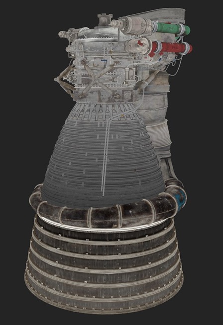
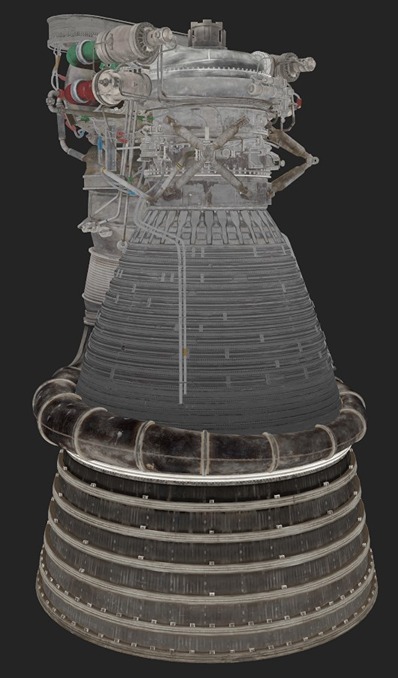
Rocketdyne F-1

Introduction
Hi! My name is Martin Martschenko. I am a self-taught 3D Environment Artist from Germany.
My journey into 3D art began with a passion for video games that started at a young age. This grew into a deep curiosity about how these virtual worlds were created, which I have been focusing on for the last couple of years.
Goals
My main goals were to improve my texturing and baking skills, so I chose a challenging project, believing that the harder it was, the more I would learn, and I definitely learned a lot from it.
-
My main modeling software for this project was Blender and ZBrush.
-
For UV Mapping, I’ve used ZenUV and UVPackMaster 3.
-
The Texturing and Baking were all done in Substance 3D Painter.
-
Marmoset Toolbag 4 for the Presentation.

References & Inspiration
Reference search is probably one of the most important stages of a project, which is why I spend a lot of time searching through the whole Internet for the idea I have in mind.
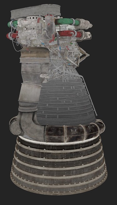
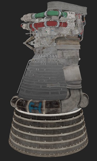
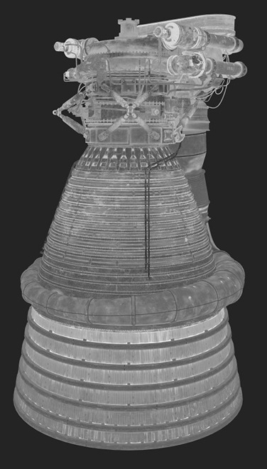
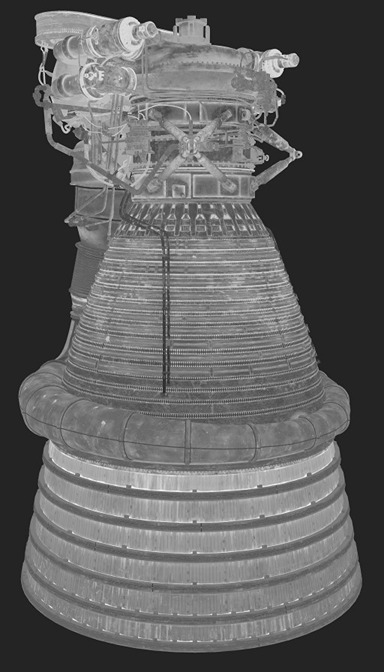
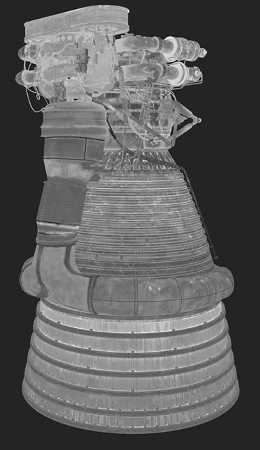
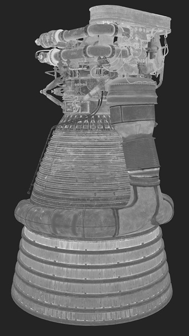
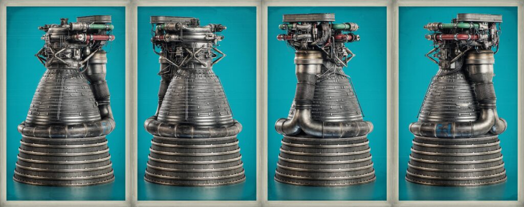
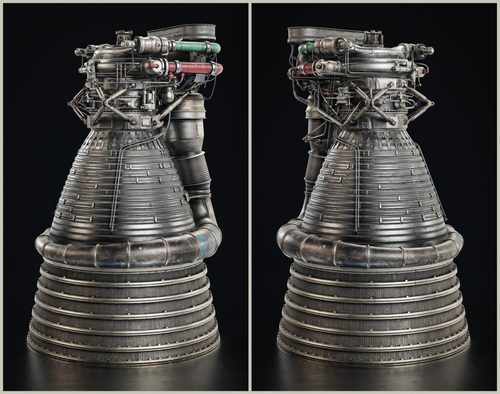
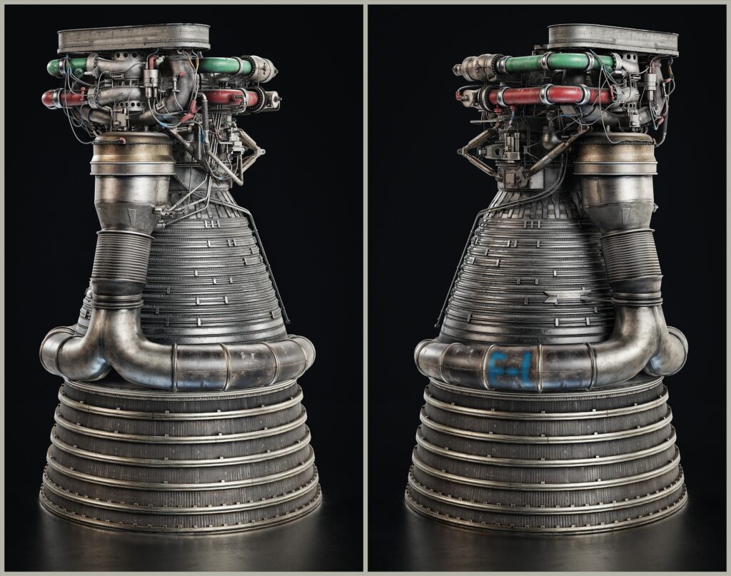
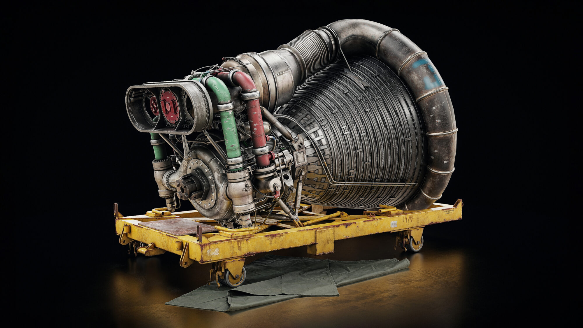
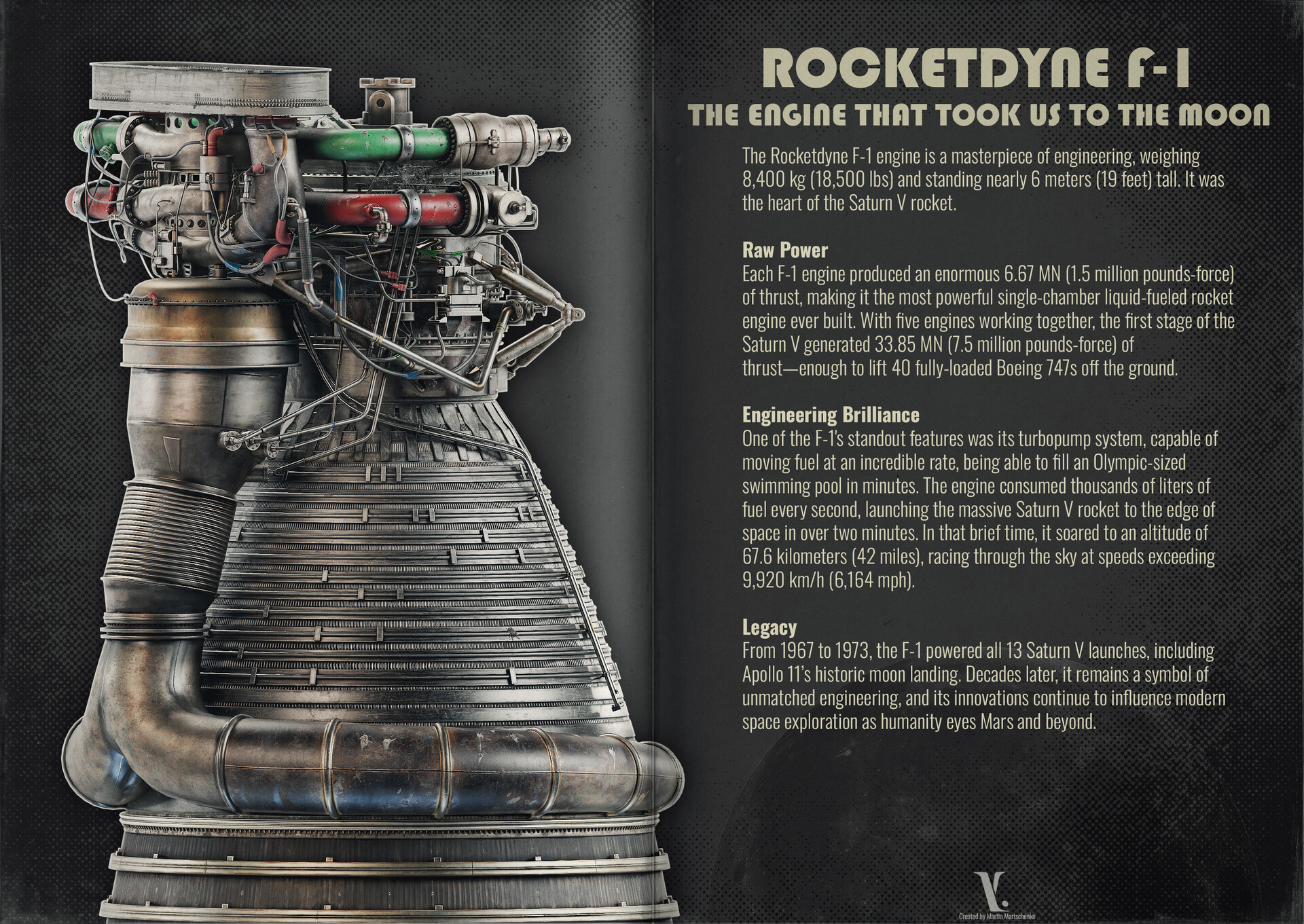
In this case, it was the Rocketdyne F-1, the Engine that powered the Saturn V Rocket.
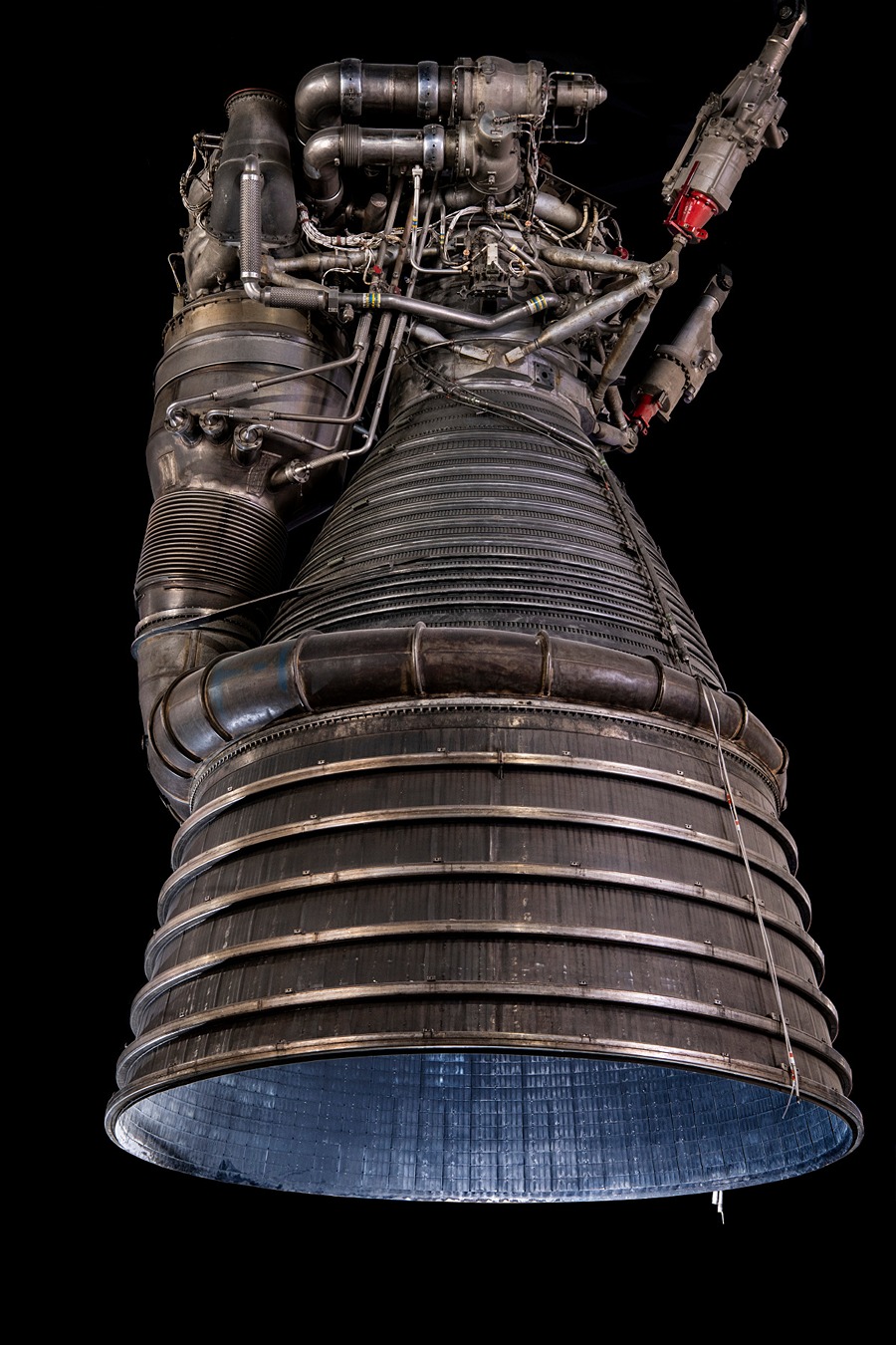
The Initial Idea came from multiple factors; I’ve always wanted to create a complex prop to practice my baking skills and was inspired by the amazing work of Matthias Develtere.
In addition to that, I watched a space documentary where I came up with the idea of recreating the iconic engine from Rocketdyne.
The first image I found on the Internet was intimidating and complex, but what I’ve learned over these years is that no matter how complex the object or the scene is, it all comes down to planning it properly.
I’ve mentioned at the beginning the importance of Reference, and I can’t stress enough to gather enough references.
Every single extra image you gather will improve the result of the project. My software of choice for reference gathering is PureRef.
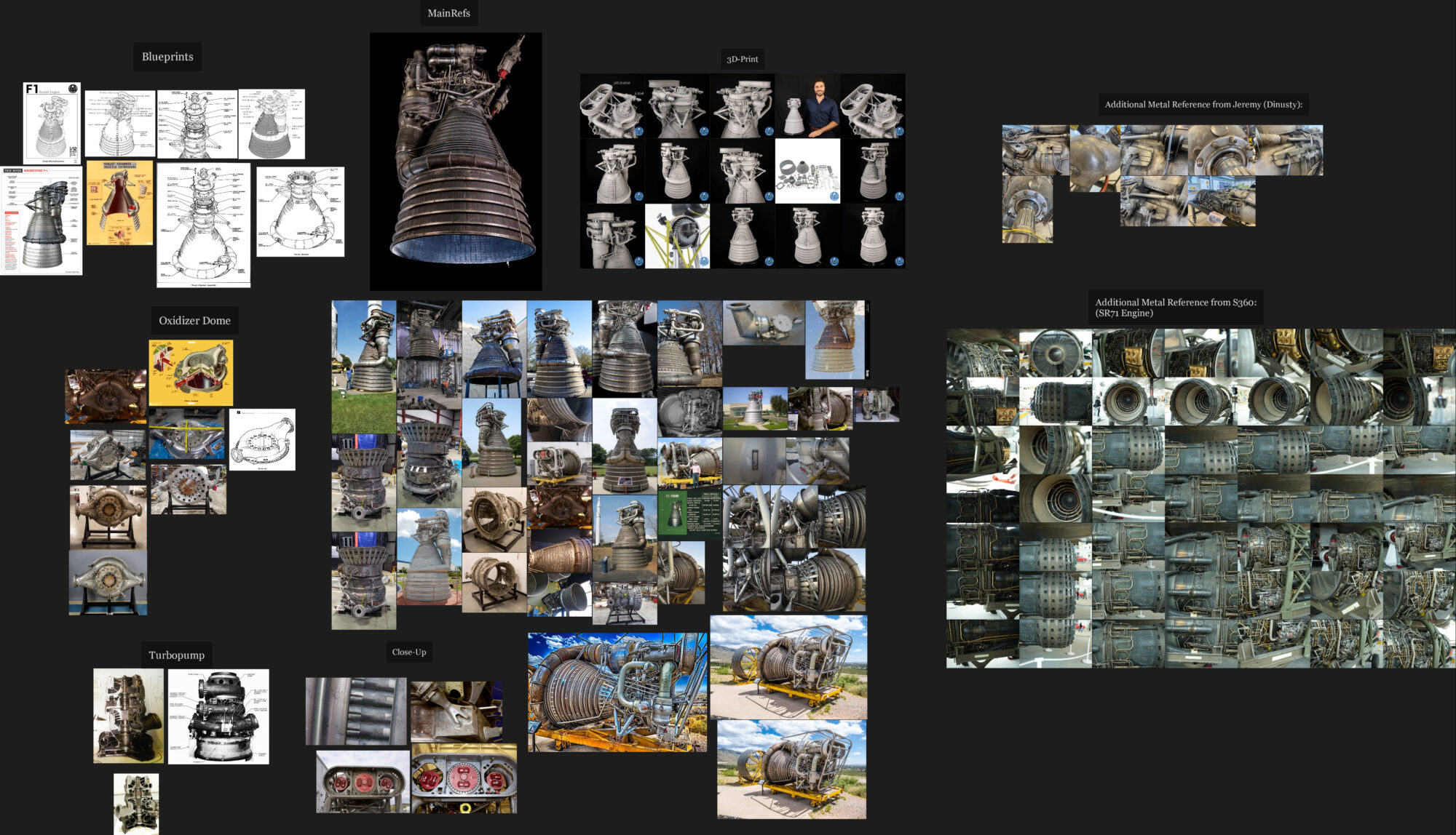
My PureRef File has a mixture of photographs, close-up images, blueprints, and even a 3D Printed Model of the Rocket Engine.
Every image you can find is helpful; I’ve also used YouTube Videos which have been a massive help.

-
Find out the name of the part from Blueprints, Research, etc.
-
Google that part and find out how it looks.
-
Look up the measurements (if not available, I am guessing based on pictures where a human is standing beside it).
-
Model a basic version of it. (Blockout)
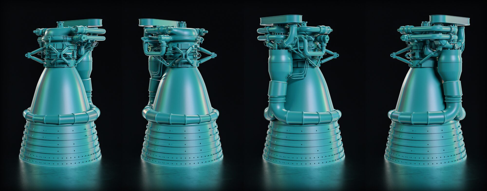
If you pay attention to the Blockout Renders, you might notice that some of the elements (like the Pipes) look differently organized than in the final model.
This is because, later in my research, I found that this Engine had a lot of different iterations where some of the elements were differently organized, which means a lot of my references were made of different versions of the same Engine.
Later, I decided to stick to the original design.
Some might say this is already too detailed for a Blockout, which it kind of is.
But personally, for Props like these, I like to add a bit more detail than usual because I knew that I would be reusing this for the Low Poly, which saved me some time and made it easier later.

-
Create a Cube.
-
Separate the Edge.
-
Delete the Cube.
-
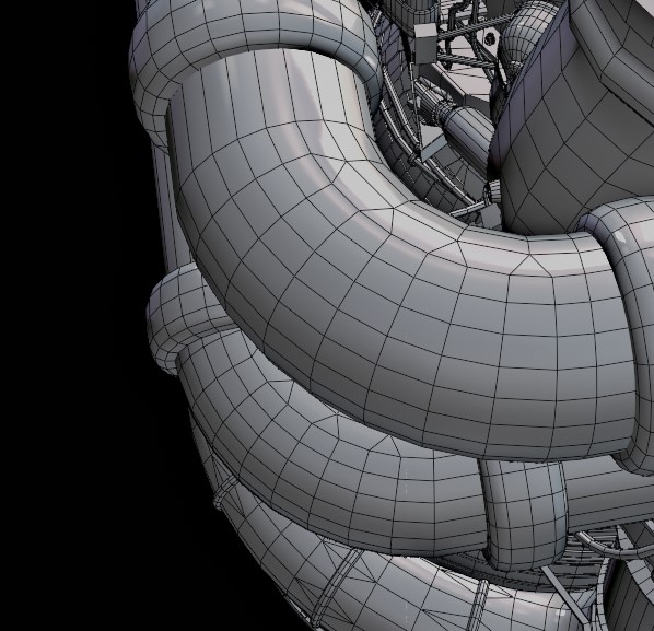
Extrude the Edge until you have your desired shape for the pipe.
-
Bevel the vertices in Blender (Ctrl + Shift + B).
-
Convert to Curve.
-
Add Depth under Curve Settings.
-
Convert to Mesh when you’re happy with it.

-
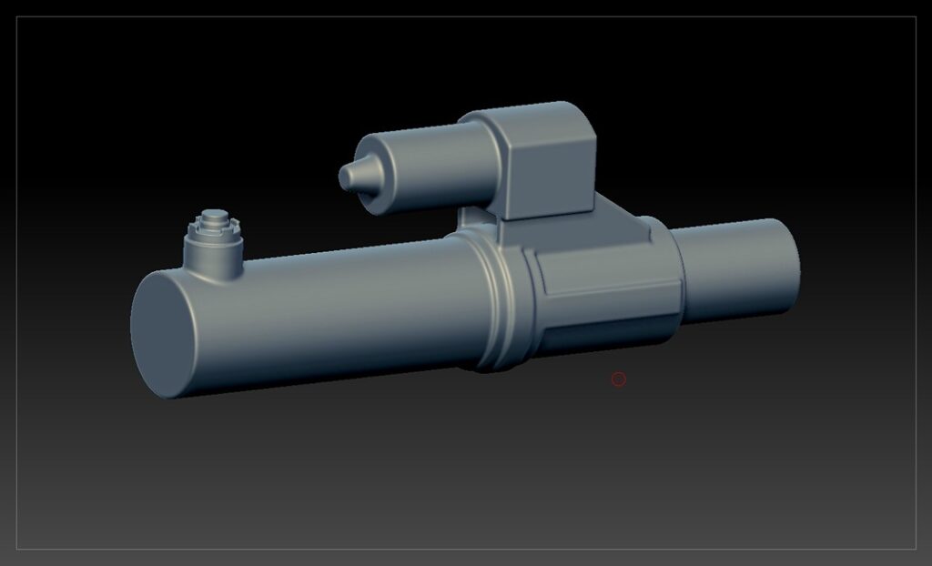
Create the shape based on your reference; as you can see in my image, it’s just a bunch of primitive shapes moved into each other. Our goal is to recreate the silhouette of our reference.
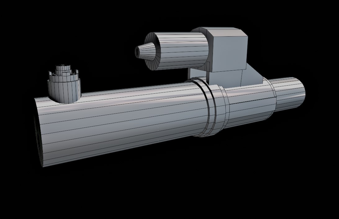
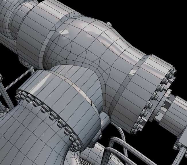
- Since we have a lot of Cylinders, we must ensure they have a high polycount, just so later in ZBrush the Hard Edges will not be visible.For that, I just put a crease on all the sharp edges and added a Subdivision Surface modifier; this will only increase the polycount of the sides of the cylinder which is exactly what we want.After that, we export it.
Make Sure to merge all your separate meshes into one like you see in the gif below, otherwise, you have to merge it in the SubTools Menu inside of ZBrush for this to work.
When we import our Mesh into ZBrush, all we have to do is activate DynaMesh; depending on the size of the mesh, the resolution you have to use is different. In my case, since this part of the rocket is quite small, it was about 1 million polygons.
Now, if you look closely, the areas where the mesh was intersecting are “connected,” looking like one mesh; if you don’t have access to ZBrush, it’s basically the same as Voxel Remesh in Blender.
The bevel still looks very sharp which is why we use Polish in the next step.
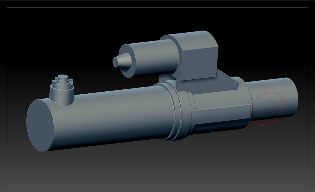
- If you go under Deformation, you can see a bunch of different sliders; the one we are interested in is the first one.If you now increase it a little bit, you can see the magic where all your sharp edges and intersections become smooth, looking like one piece of mesh.
Note
If you get into a situation like I did with this mesh where you have smaller parts and therefore need smaller bevels only in that area, in that case, I always only apply a small polish and mask the area where you’re happy with the bevels.
Then afterward polish again to create a bigger bevel on all the other areas which are not masked.
-
All you have to do now is to export it back to your software of choice. I still highly recommend decimating your meshes before exporting inside of ZBrush with Decimation Master, just so you avoid having 10GB FBX files or Blender exploding.
This workflow is extremely powerful and saved me a ton of time. There were cases when I used the traditional method since sometimes it’s easier to do it that way. I still highly recommend learning both ways and using whatever saves you more time.
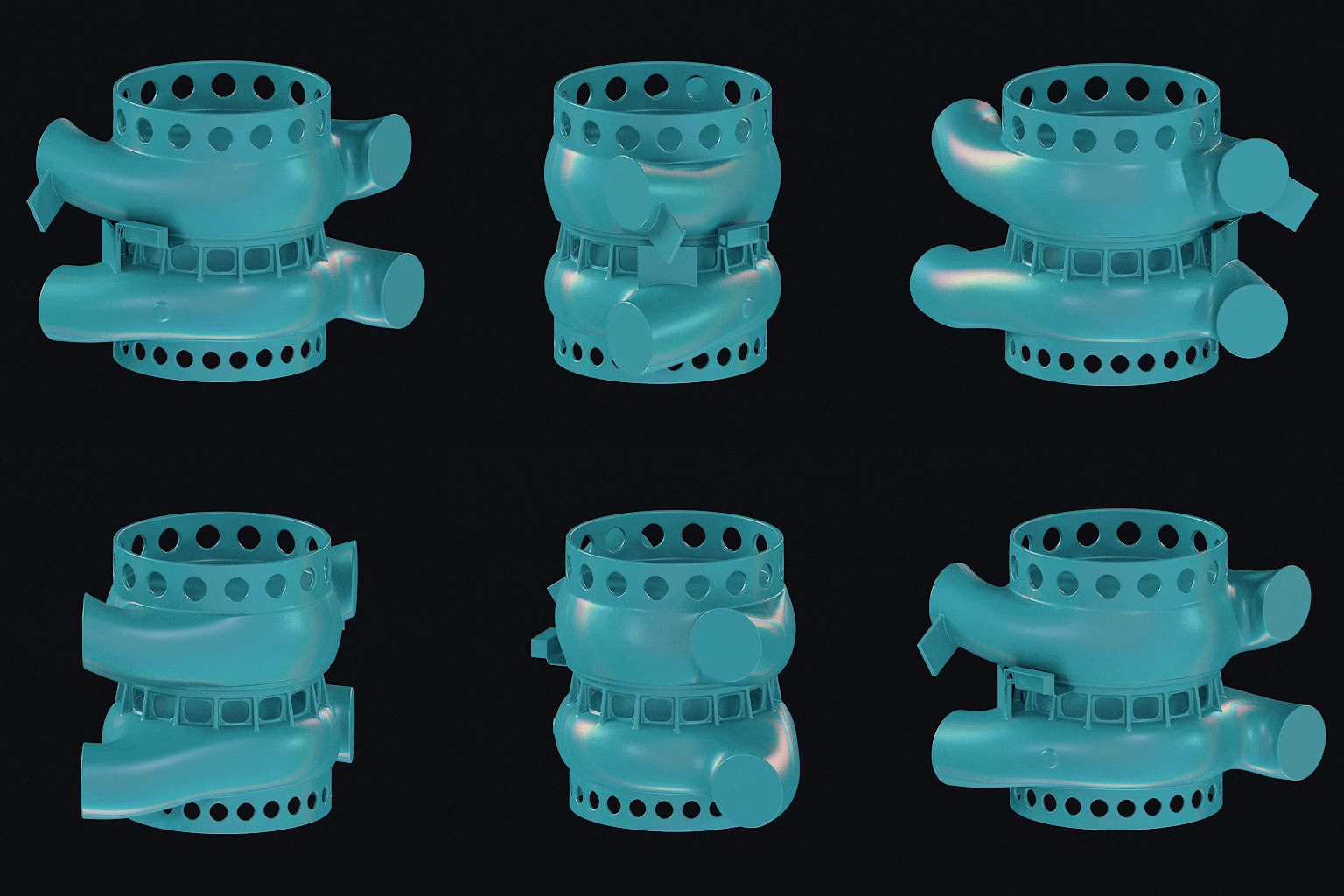
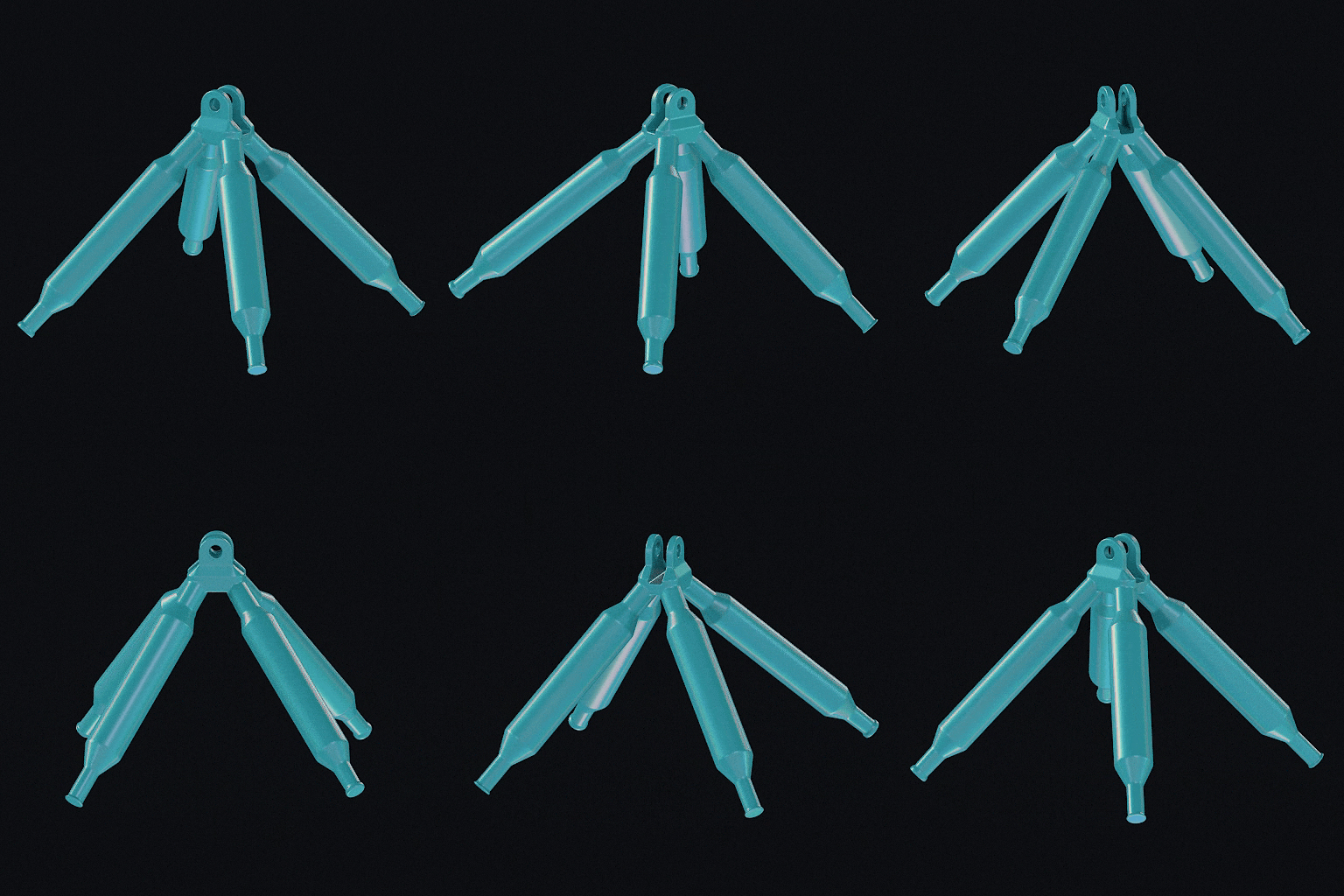
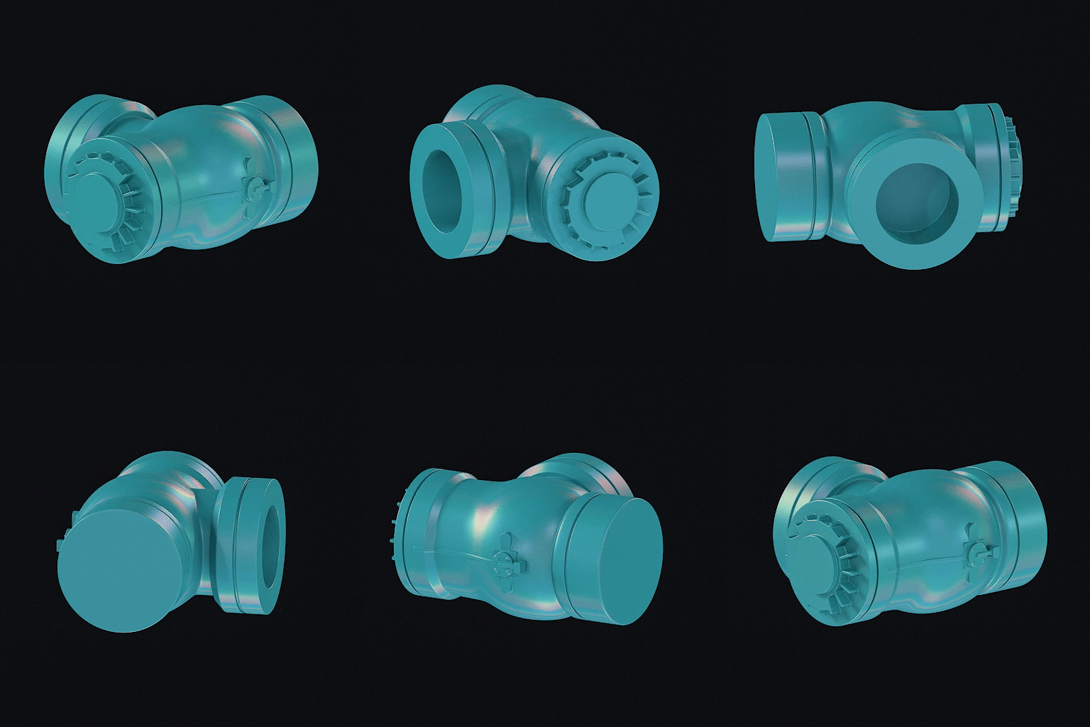
Below, you can see a couple of High Poly Meshes of the Engine that have been created with this workflow:
Welding
Let’s talk about the Welding Seams as they are also a crucial part of this model. Most of these weldings were created with the help of an amazing addon from Łukasz Hoffmann called “Welder” Link to Welder addon.
This addon allows you to create welding seams from a bunch of different presets inside of Blender between two intersecting objects with just a couple of mouse clicks. This Addon combined with the workflow I’ve mentioned above created some amazing results at an incredible speed.
Sculpting Weldings can be quite time-consuming, especially if you have a lot of them like I had in the Rocket Engine, which is why I’ve used this addon to save some time.
There were cases where the weldings in the Reference were quite unique, and the addon couldn’t replicate the look of it, which is when I sculpted them manually. But for the typical weldings you see on 90% of objects in the real world, this addon is a huge time saver.
Below you can see the photograph of one of the weldings I had to sculpt manually in ZBrush.


Low Poly
Low Poly creation is all about silhouette; our goal with a low poly mesh is to give the viewer the illusion that they are looking at a high poly mesh, even though they are looking at a heavily optimized one.
We achieve this by reducing polygons where the viewer can’t see it, and the silhouette plays a very important role in this.
I knew that I wanted a really optimized model in terms of topology, so just using decimate and calling it a day wasn’t an option. This would have created a whole bunch of other problems like unoptimized UVs or thin triangles.
So, for the whole Low Poly, I’ve reused the blockout and always compared it with my high poly. If I see details in the high poly that affect the silhouette, I remodel them in the already existing blockout mesh with optimization in mind.
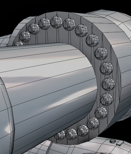
The Engine is 90% made of Cylinders, so I made sure to optimize them in a proper way by reducing the polygons based on the diameter of the Cylinder.
If you look at the illustration below, you can see two different cylinder caps with a hole in the middle; usually, a hole inside a cylinder will have a smaller diameter than the base mesh, which means the smaller the diameter is, the less polygons you need for the silhouette to be smooth.
The 32 Triangle difference between those two meshes might not seem like much, but considering the huge number of Cylinders I had in this Engine, this saved a lot. The same applies to bent pipes; the smaller the bend radius, the fewer polygons you need.
I’ve used this method over the whole Rocket as shown in the images below.
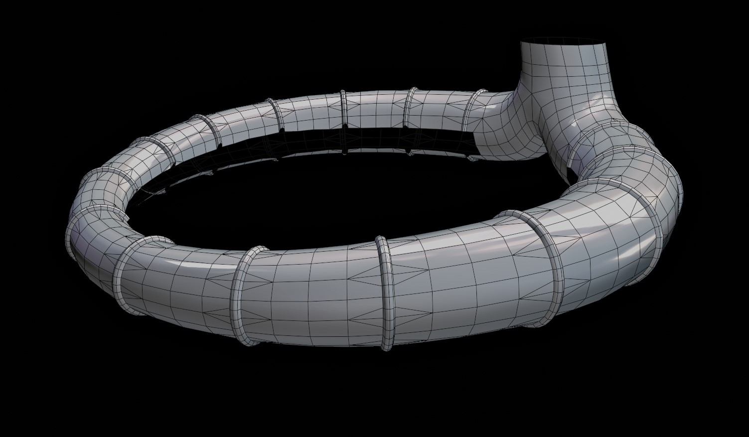
You can especially see this on the big pipe of the Engine.
Because I always optimize with silhouette in mind, I’ve only increased the Polygons of the rings which basically block the view of the actual pipe in the silhouette, making my eyes think that I am looking at a mesh with a high polycount, even though the actual pipe has quite a low polycount.
This is because you only really see the rings in the silhouette. I’ve also deleted faces that are hidden and not visible; this not only saves polygons but also in the end gives you more UV Space to work with and therefore a higher texel density.
If you like to read more about this type of stuff, I highly recommend this short article by CGTyphoon that covered these optimization methods in detail, which I’ve used over my whole model: Link to CGTyphoon Article

UV Mapping & Baking
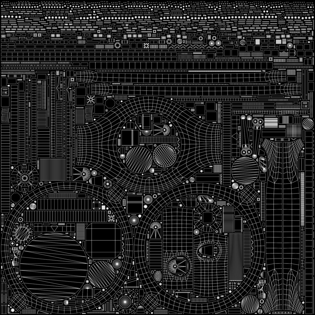
Now, I think it’s very important to mention that in terms of UV Mapping and Texturing, a Prop of that size requires a lot of unique UV Maps to achieve the desired texel density and therefore is extremely unlikely to be ever used in a game in this state.
If you would create a prop like this for an actual game, a combination of Trim Sheet, Decals, and Masks would have made a lot more sense, but in my case, as mentioned at the beginning, my focus and goal was to improve my baking and texturing skills.
For that, I chose a complex model with the thought that if I’d be able to successfully bake and texture an asset this size, I would be able to bake any asset in the future without any issues, and for that purpose, I’ve definitely learned a lot from this project.
With that being said, the target texel density for this project was 1024px/m, which allowed me to have crisp details and more possibilities for adding interesting materials in the texturing process.
I see a lot of people who take Texel Density too strictly when in reality you do have some flexibility. I like to see Texel Density as a guideline and not a rule; for this model, the Texel density was between 900px/m and 1100px/m. If it doesn’t look weird or is too noticeable, it’s fine if you don’t have exactly 1024px/m.
In terms of the actual UV Mapping process, I use a bunch of addons that make my life easier since Blender’s native UV Tools are not good in my opinion. The main ones are ZenUV and UVPackmaster 3.
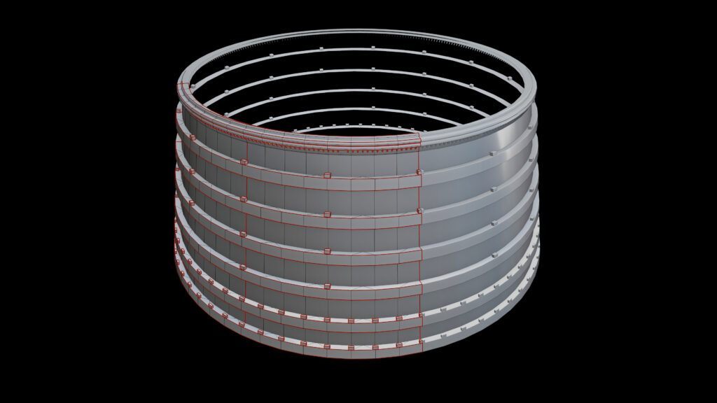
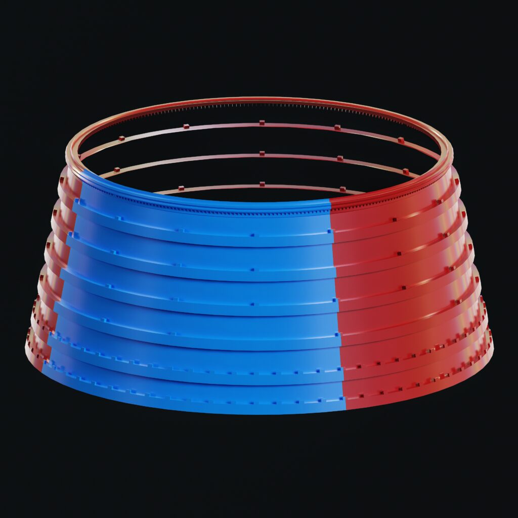
Because the Rocket was made of a lot of Cylinder Shapes, and I wanted to save as much UV Space as possible, I’ve only UV’d ¼ or ½ of the Cylinder and stacked the rest; a lot of the models are also mirrored, which saved some time in the modeling process as well as saved more UV Space.
Below you can see an example of this with the Nozzle Extension and the Top Part.
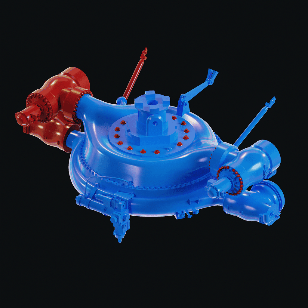
The Blue Color shows the actual UV which is in the 0-1 space, whereas the red color shows the UVs that are stacked on top to save space.
UVPackMaster 3 was an incredible help for this one due to the amazing packing as well as its “Split Overlapping Island” feature that moves all the overlapped islands in the next tile for baking purposes.
This is done across the whole model, which saved me a lot of UV Space and therefore I could achieve a higher Texel Density. Since the whole model is basically textured with presentation in mind and not necessarily for games.
I’ve also decided to use a smaller Pixel Margin just so I can get even more Texel Density, which then again, I don’t recommend if you would actually create an asset for an actual game. In terms of the baking, it really isn’t anything special.
Personally, in the past, I’ve used Marmoset Toolbag for baking, but in my opinion, I find Substance Painter’s Baking Tools really good nowadays, so I just bake there. Just so I don’t have to switch between software all the time. I didn’t really use anything special like name suffixes since it worked without them.
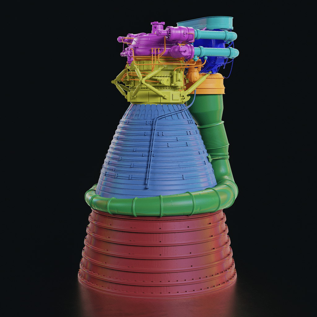

Texturing
We have come to probably the most interesting stage; it’s time to give the engine some color and make it look realistic.
Before we talk about the actual texturing process, I want to mention the importance of planning and studying the materials because this will greatly improve your work and give you more flexibility.
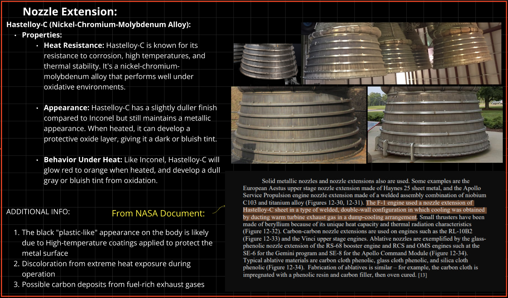
You might ask yourself why you should study the materials if you can just create some random metal material or some metal that looks similar to the reference and put it on the object, but the truth is that no object is made out of some random metal.
It’s made of a particular metal that suits the needs for this exact object, and each metal has its own properties on how it reacts to heat, dirt, water, etc.
If you know your materials and how they react, you will know where you should paint the imperfections and, most importantly, how the imperfections should look.
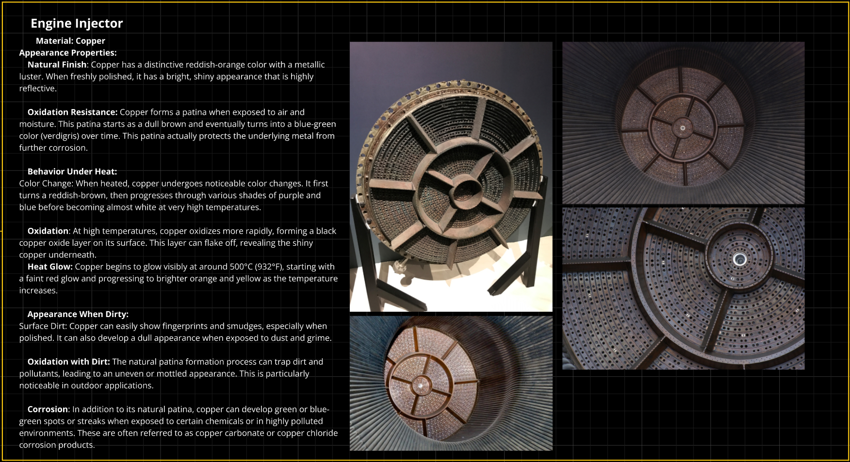
My Favorite Website for planning is “Miro”. Below you can see a screenshot of the layout of the planning in Miro. I will cover each section in detail and explain why I did it like this.
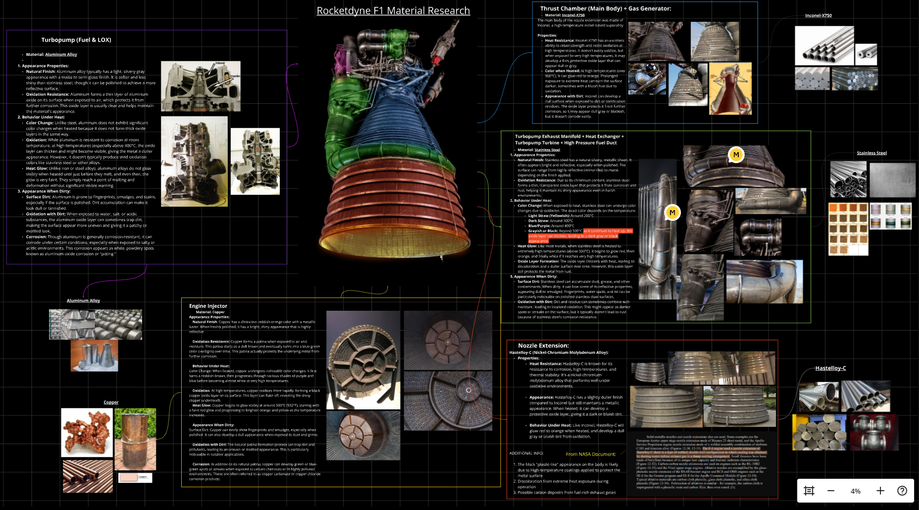
It’s easy to get overwhelmed by the vast number of materials, so breaking it up into its own sections helped to organize it all.
-
What is the appearance of the Metal? How does it react to Oxidation?
-
How is the behavior under heat?
-
What is the appearance when dirty?
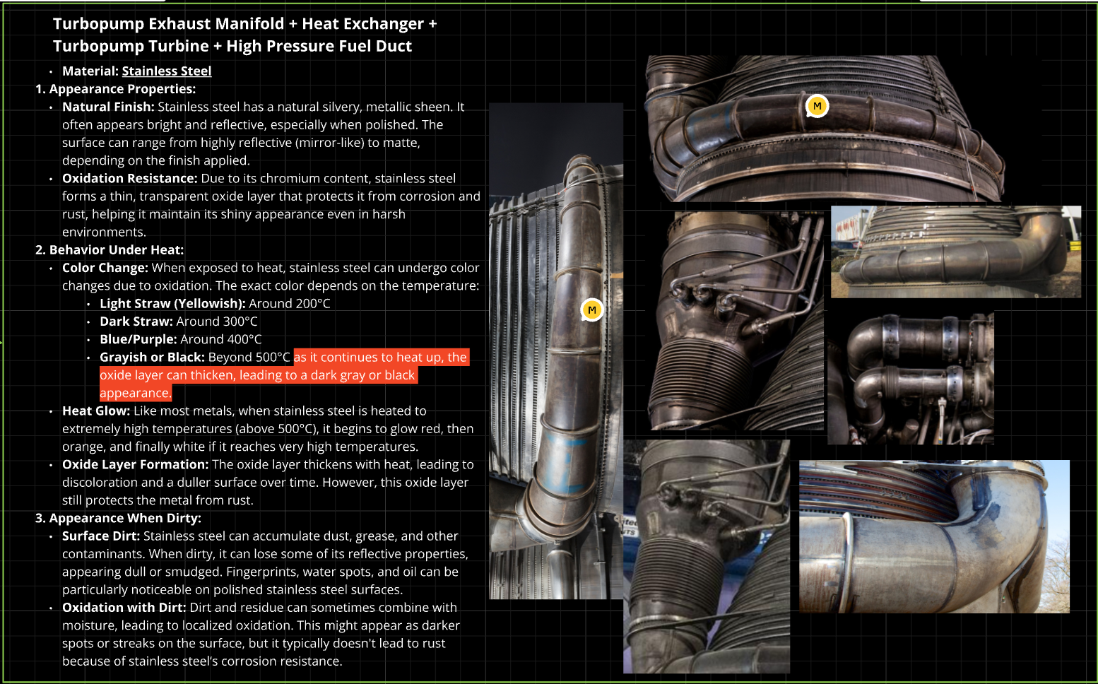
This was unbelievably helpful for me to know why exactly the Metal looks like this in the Reference and how it happened.
This knowledge is not only helpful for the actual material creation but also if you plan to not follow your reference or if you don’t have enough references and must add your own details which are not existent in the reference.
If you understand the materials, you know where to paint the imperfections and how they should look.
An advice most of us probably have heard once in a while is to get enough reference, and it’s honestly one of the best pieces of advice out there in terms of 3D Art.
Reference is one of the key factors, especially if you’re aiming for realism.
But I believe in addition to gathering a ton of Reference, understanding the reference and understanding why it looks like this opens you up to so many more possibilities and therefore improves the result.
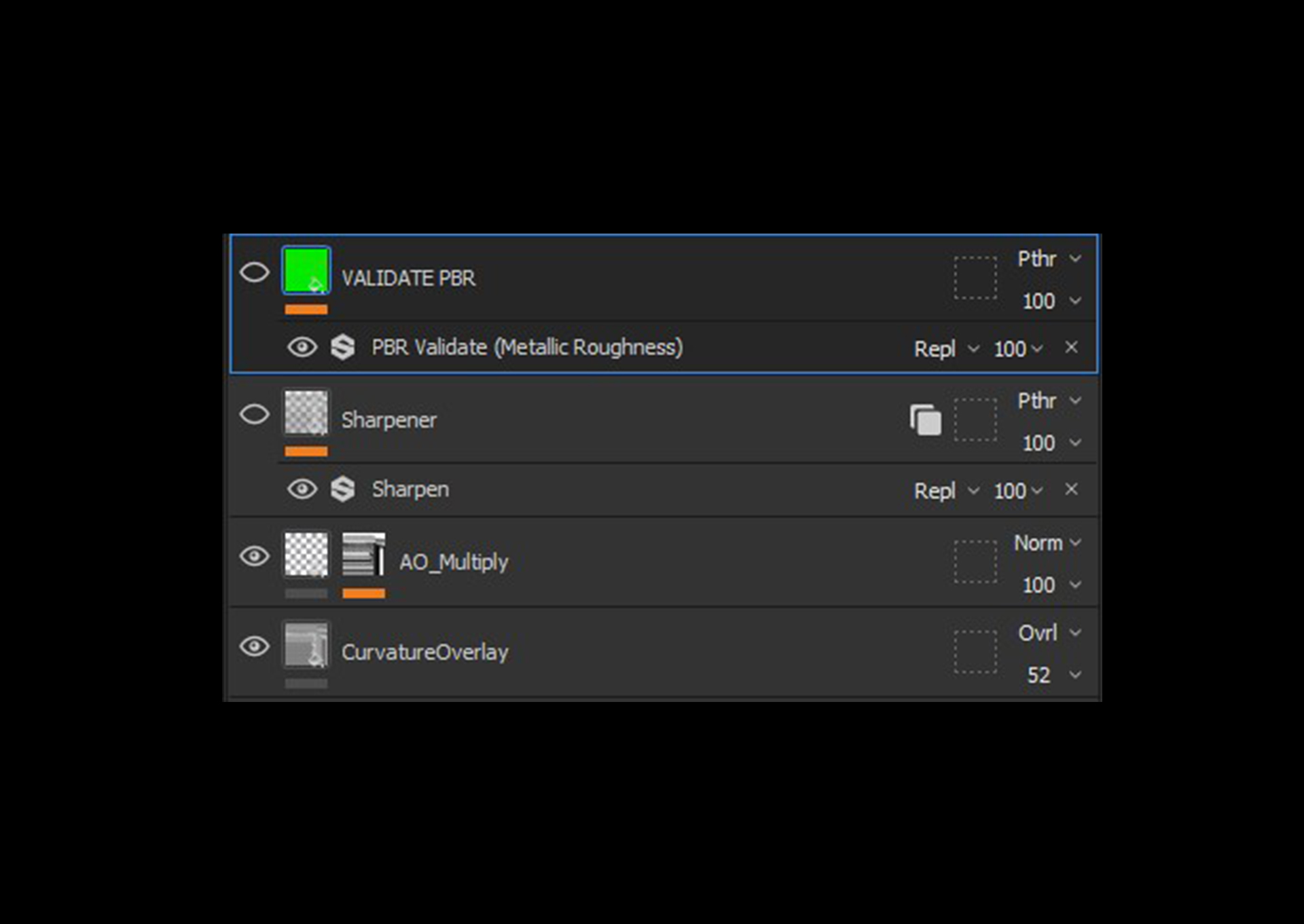
After importing and baking my Mesh in Substance Painter, I follow a base set up in every Texture Set in the Layer Stack before starting to texture the object.
-
First, I have a Curvature Overlay, which is basically the Curvature from the Baked Mesh overlaid in Color. This effect produces brighter edges while making everything else darker. I found that this effect makes the texturing more contrasty and nicer to look at.
-
Above that, I multiply the AO Bake Map of the Mesh; this again just adds more contrast and makes the AO Map stronger.
-
At the top, I have a Sharpener, which is just a Passthrough Layer with a Sharpen Filter. Sometimes I don’t need it, but sometimes it can be quite helpful. The con is that it can quickly make your materials look noisy, so be careful with that.
-
Above everything, I have a PBR Validate, which ensures that I have the right PBR Values. Depending on the Mesh, I disable or enable some of them.
-
I also use a LUT from Alexandre Alves in Substance Painter, which matches the colors as accurately as possible to Unreal Engine 5. I found that this LUT is a little more accurate in comparison to setting ACES in the Viewport Display in Substance Painter, but both methods work well.
Here’s the LUT: Link to the LUT
-
Color Variation
-
Roughness Variation
-
Height Variation
As mentioned earlier, there are a lot of weldings on this Engine, especially smaller ones. Doing them all in the High Poly would have taken a ton of time, so I decided to do it in Substance Painter and at the same time use the power of Anchor Points, which have been heavily used in this Project.
Substance Painter has an amazing tool that I’ve used on this Project for the small weldings called the Path Tool. To explain very simply, it allows you to create a spline on top of your model where you can assign Materials that will follow this spline.
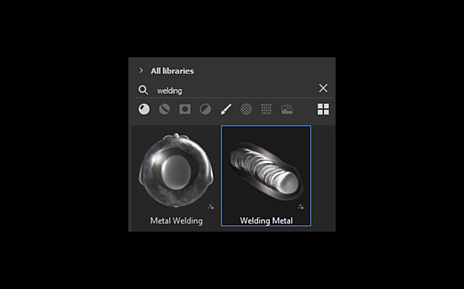
You can actually try it out right now since Substance Painter already has a Welding Path tool inside their library, which I’ve used for this project.
If you just search for “welding,” you will find “Welding Metal”; if you click on it with an empty layer, you will automatically be in the Path Tool, and you can start creating them on your model as shown below.
After creating all the Weldings I wanted, I put an Anchor Point on this layer because I wanted to create dirt based on these weldings, just like in my Reference.
The dirt for the Weldings has quite a complex setup because I wanted as much variation as possible to avoid making it look repetitive, so it has a lot of filters and different Grunge Maps as shown in the breakdown below.
The same technique was used on the weldings of the bigger pipe:
Anchor Points really do bring your projects to the next level; my favorite combination is using Anchor Points and the High Pass Filter, which allows you to add multiple layers of complexity to your materials, which is what you see a lot in the real world.
I generally spend a lot of time in the mask trying to replicate my reference as accurately as possible; for that, I use a mix of generators, stencils, and hand-painted details as shown in the example below.
My favorite Stencils Pack that I’ve used for this project is from Javad Rajabzade called “Metal Surface Imperfection Vol 02”; apart from that, I’ve also created my own stencils from my reference.
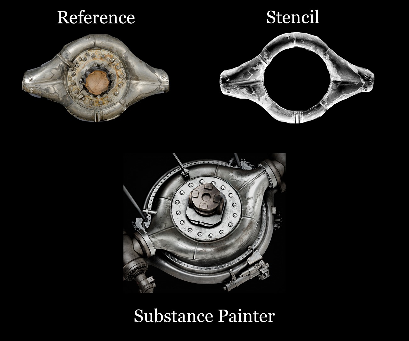
Basically, for the Stencil, all I did was take my Reference in Photoshop, desaturate it, and increase the Contrast. After that, play with levels to get good black-and-white values, and you’re done.
Now you can import that in Substance Painter and paint it on your mesh; I still fixed and hand-painted a lot of extra details on areas that seemed too empty or the stencil couldn’t reach.
Originally, this project was just supposed to be the Engine alone, but after getting some critique that I should add more color, I did by making the tapes different colors and even making the bigger pipes at the top.
Which originally had been just bare metal and had green and red paint, I still found it to be a bit colorless and not interesting to look at, so I decided to model a cart which I found on some Reference pictures as shown below.
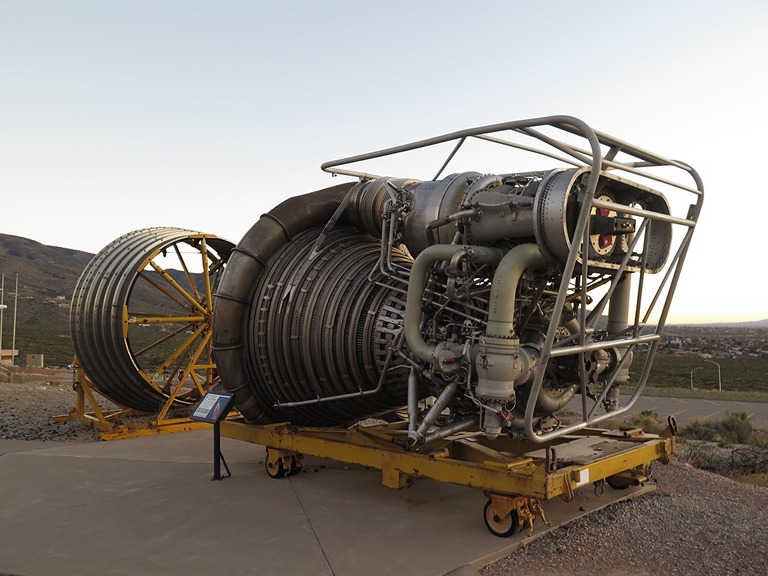
The cart was done roughly in about 1.5 – 2 days, but for that, I think it turned out quite well.
Modeling-wise, it’s nothing special; for the high poly, I haven’t done any sculpting; all I did was just take the low poly and bevel some of the edges and add some welding with the Addon I mentioned above; the texturing does most of the work here.

Presentation
In terms of the Presentation, I think that Marmoset Toolbag is just the best software out there for this type of stuff; it’s incredibly easy to use and produces really good results in a short period of time.
I see a lot of props or environments on ArtStation where I can see that the texturing and the assets look really good, but the lighting and presentation just don’t show it to its fullest potential, which is such a bummer considering the amount of time you’ve spent adding all those details, so definitely take your time with the presentation.
Lighting
When it comes to Lighting, I think for Props like these, basic is best. For this one, I just used 2 different HDRI from PolyHaven, one being an Interior Lighting (for the renders with the cart) and the other one being just a basic studio (for the full rocket engine standing).
I also use a Shadow Catcher with a Roughness Map just to get some nice reflections on the ground and add more shadows.
In terms of the Render Settings, I’ve used Ray Tracing and used a lot of bounces as well as put the Shadow Quality to the maximum. I wanted the highest possible quality for my final renders.
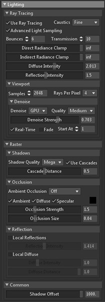
Camera settings
I feel like the Camera Settings have the biggest impact on the overall visuals because that’s where you can add some Post Effects and change your Tone Mapping.
In terms of Tone Mapping, I always use ACES; it’s just what looks best for me and is closest to my Substance Viewport because of the LUT I am using.
For the Lens, most shots use 50mm to represent the human eye the closest; play around with some lenses and see what works best as this can have a huge effect on how you see the model.
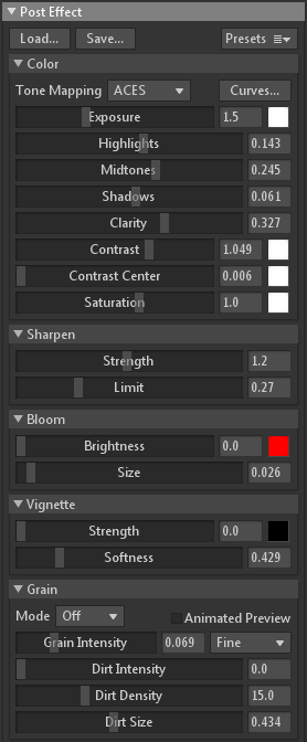
You might notice that I don’t use any Vignette or Bloom; this is because after Rendering it out, I usually import the images in Photoshop to do some last changes there because that’s just where I have more possibilities and what I am used to in terms of post-processing.

Conclusion
First and foremost, I would like to thank everyone who supported me during this Project and gave me critiques to improve it. I would also like to thank Games Artist for this opportunity; I really appreciate it!
In conclusion, I can say that this project has been an amazing learning opportunity for me to improve as an artist. I feel like the goal with every personal project should be to go out of your comfort zone and create something you haven’t done before, because every time you do so, you will drastically improve as an artist.
Thanks for reading – I hope this was helpful!
