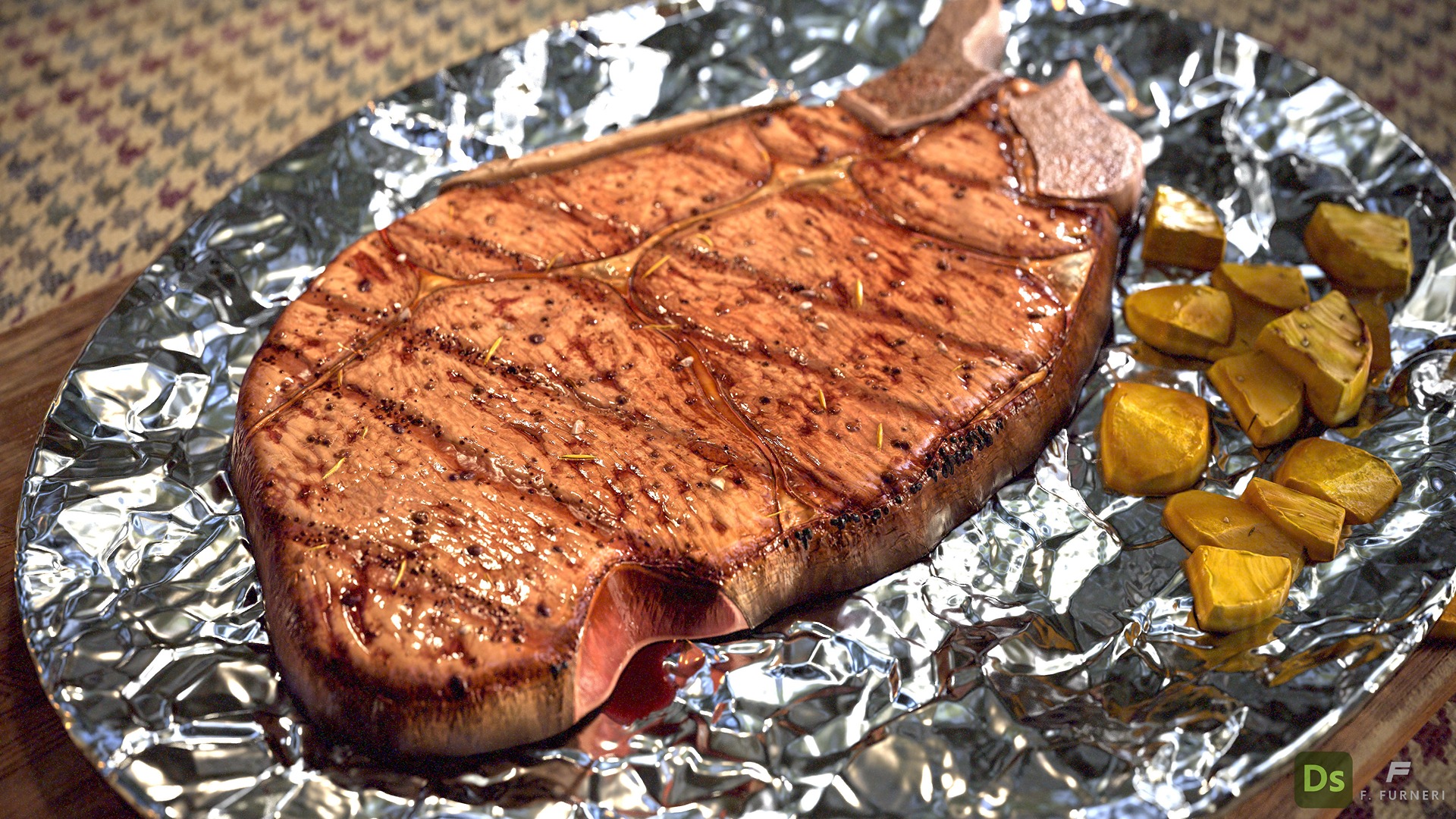
Grilled Steak

Introduction
Hello everyone, my name is Francesco Furneri, and I am a 3D Texture Artist from Italy.
My passion for 3D art has allowed me to work in this field for many years, primarily as a 3D Modeler and Texture Artist. During this time, I have worked on numerous commissioned projects from studios.
I also have professional teaching experience in 3D lighting and rendering in the U.S. and have contributed to several articles for the artist community, which are accessible from my LinkedIn profile.
I am currently employed as a 3D artist and also freelance, providing professional 3D props for games and films.
Project and Goals
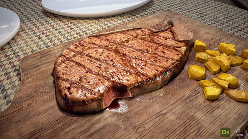
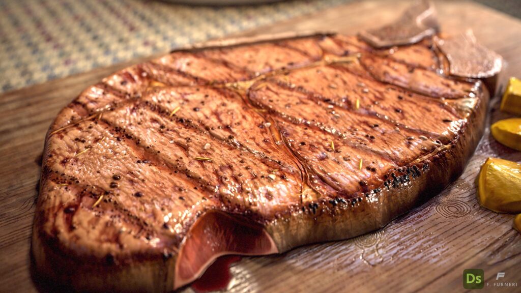
In this article, I aim to explain a bit of my workflow involving the creation of a procedural grilled steak.
This is a personal project where I wanted to achieve something different from my previous works in 3D Substance Designer.
The goals were to:
- Practice more with organic shapes in the Designer.
- Create something realistic and, at the same time, visually appealing and appetizing.
All of this is achieved without traditional poly modeling techniques. What you see is entirely procedural.
Also, one of the biggest challenges was adding the right level of detail by layering the different parts, as well as adopting a different “modeling” approach.
Finally, I wanted to demonstrate that, in addition to creating tiling materials, 3D Substance Designer is also a valid solution for certain types of props.
One of the biggest advantages of modeling in Designer is its non-destructive workflow and the ability to build material variations quickly.
Tools
- Substance 3D Designer: Used for creating bitmaps (albedo, roughness, normal, height, etc.)
- Marmoset Toolbag 4: For set dressing, lighting, and rendering
- DaVinci Resolve: For compositing a short clip
References & Inspiration
When starting a new project, I always gather photo references to capture the essence and details I intend to represent.
Producing a juicy grilled steak is an art form — both in real life and 3D — and its final look depends on factors such as the type of meat, cooking temperature, toppings, and the presence of bones and grease, to name a few.
I used PureRef, as an image viewer, to collect the most relevant references from the Internet.
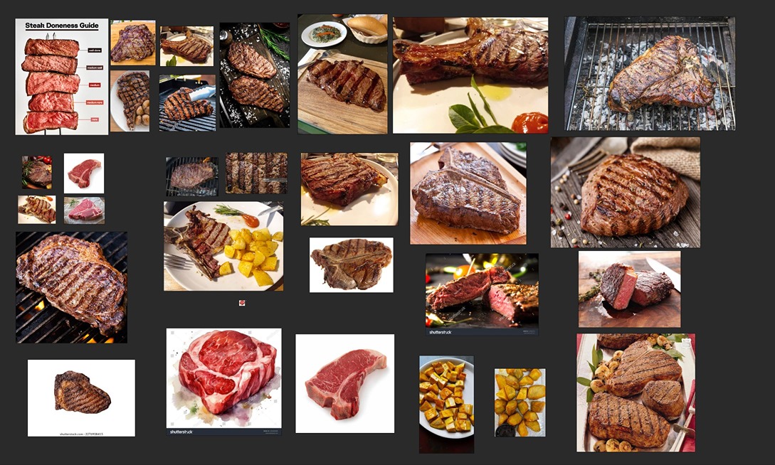
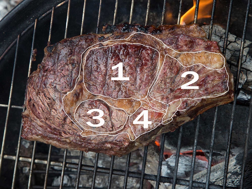
Each photo serves its own purpose: for instance, the first photo (Steak Doneness Guide) helped me study the main meat pattern and create a slight variation to apply throughout my steak.
On the other hand, raw meat has been useful just to observe the grease distribution.
The goal was to focus on a few meat features and aim to represent them entirely with procedural techniques.
Here is the list of the main elements I chose to detail and include, based on references and personal taste:
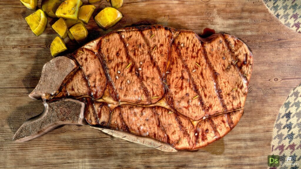
- An interesting and natural meat pattern for both the top and side parts of the meat, with random scaling and shape variations
- The presence of a few bones
- Different toppings, such as salt, spices, and burnt elements
- Certain grease areas that enhance the meat’s flavor and tenderness
- A few grill marks, indicating the steak was cooked on a hot grill
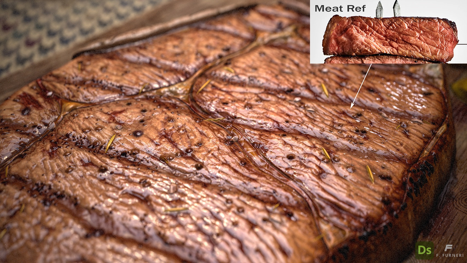
- A small cut revealing the steak’s doneness
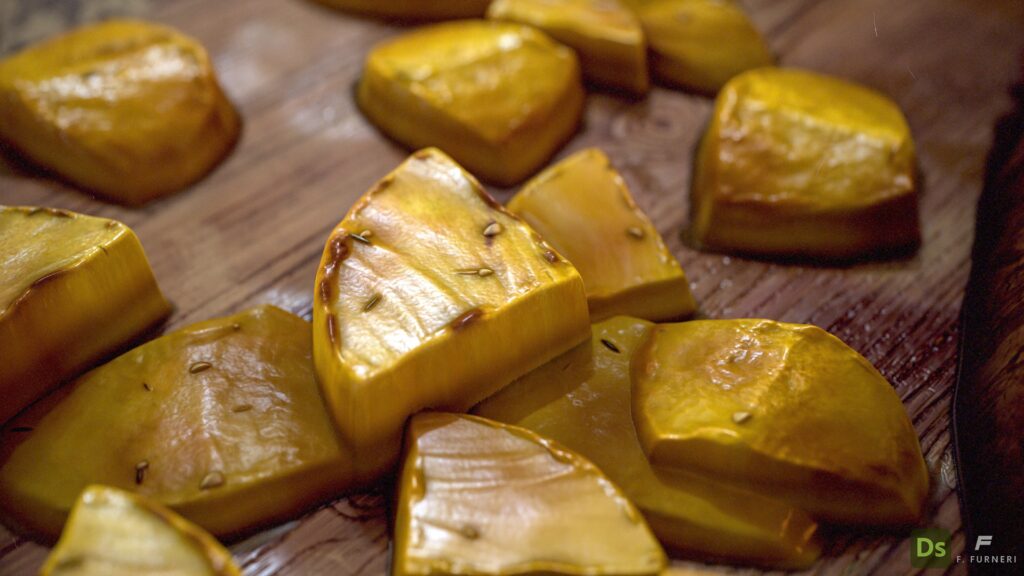
- Some roasted potatoes as a side dish
A word of advice: spend some time collecting references and discovering details for features you want to represent.
Start with a substantial number of images and then narrow down the list to the most significant ones.
Additionally, enhance your product by looking for distinctive features, such as the cut that reveals the steak’s doneness. The result will definitely be more engaging than having a simple slice of meat.
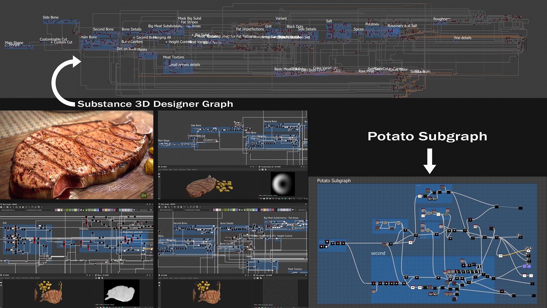
Main Material Creation
When creating PBR textures in 3D Substance Designer, it’s common practice to start with the Heightmap, which holds the extruded details.
I organized the graph with comments to make it more readable.
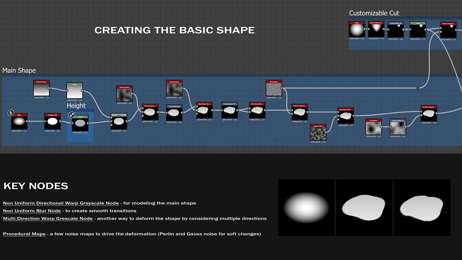
Basic Shape
As a rule of thumb, I always consider big shapes first and then move to the details afterward.
Jumping straight to details is not a good practice because you primarily need to have a solid surface to work on — the same concept applies to digital sculpting.
Now, we’re going to look at some of the graph features that are definitely useful for understanding how I built my steak.
Starting from a paraboloid shape, I used a few noise textures to drive the main shape’s deformation. The Non-Uniform Blur node, which uses the same map for both inputs, is great for creating a smooth gradient around the shape’s edge.
Note how the procedural noise maps I adopted are suitable for this kind of soft deformation since they do not contain high-frequency details.
Bones
An interesting and easy way to model two of the three bones involves using a Directional Warp node to set the direction of deformation and a Shape node with a crescent pattern to define the deformation type.
Nonetheless, choosing that circular map is the result of different tests. None of the previous maps I tested were suitable for a natural bone shape, and using many nodes is not always the best approach.
Sometimes, fewer nodes with built-in functionalities can make the work easier.
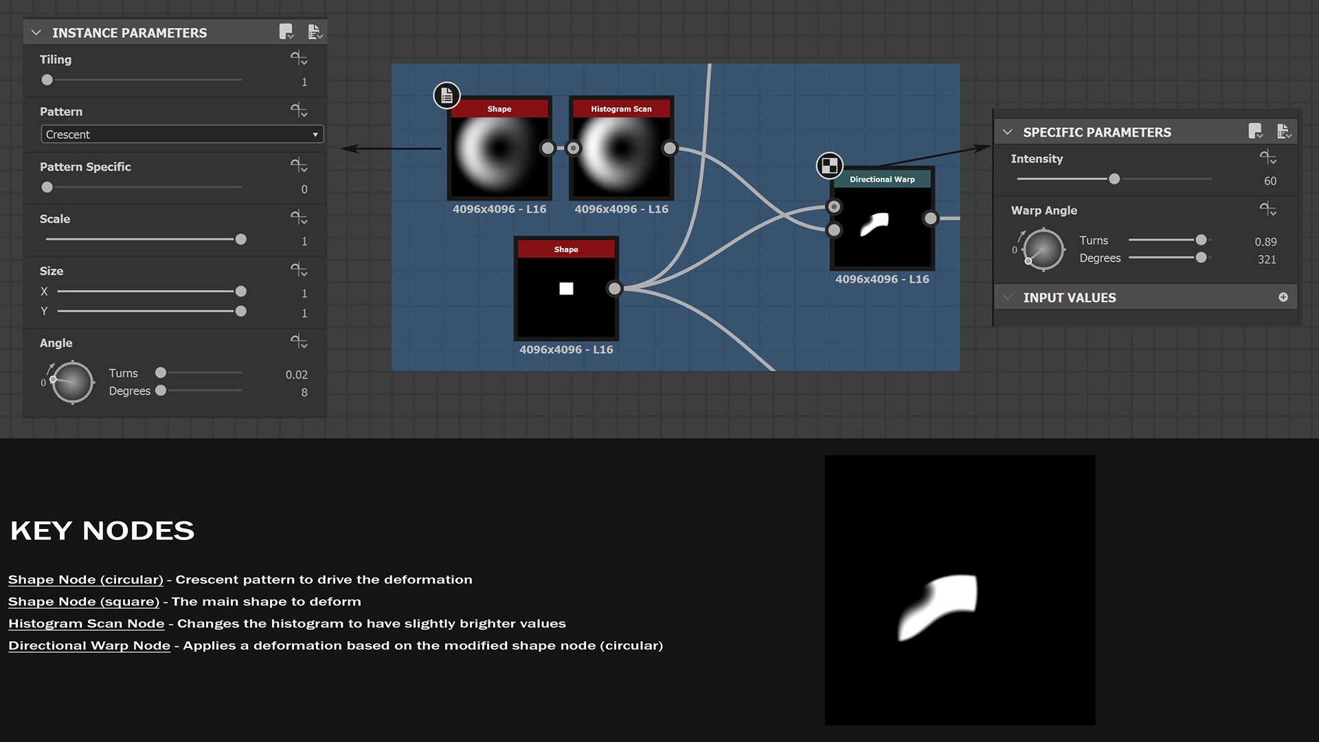
That was the starting point for this basic bone shape.
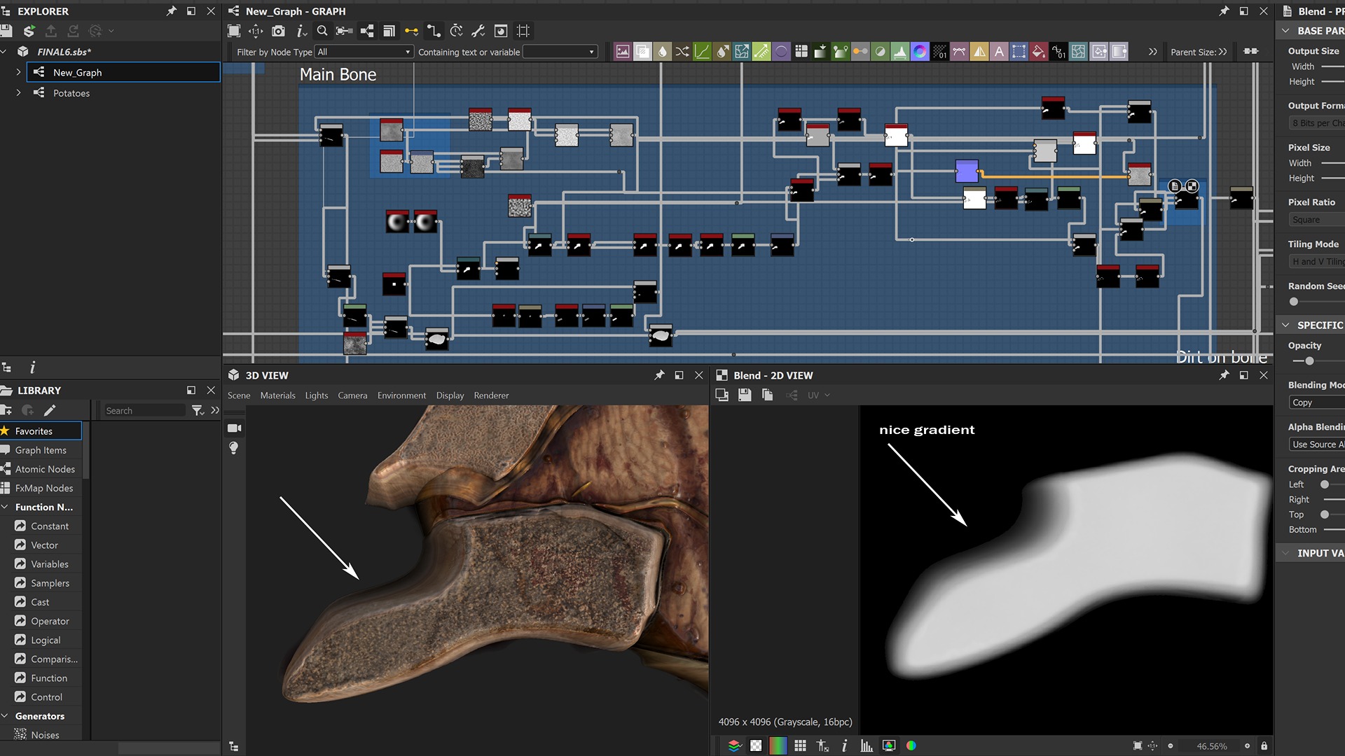
The entire graph allowed me to refine the result and achieve a more natural look. However, the smooth gradient from the top to the base comes from the initial shape node with a circular pattern, not from later adjustments.
Therefore, establishing a robust basic shape first is crucial for success—there’s plenty of time to add details later.
Greasy Areas
Not all steaks are the same! But if the steak is tender, it might exhibit some grease, as shown in the following reference.
Nonetheless, I didn’t want to exaggerate with it, nor keep that thickness in the greasy areas.
I preferred a slimmer version with a custom organic look.
In this example, the grease creates four sections that appear to be “islands,” separated from each other.
With that in mind, and after studying several solutions, I found a proper subdivision with an organic appearance. But how can you properly create it in Designer?
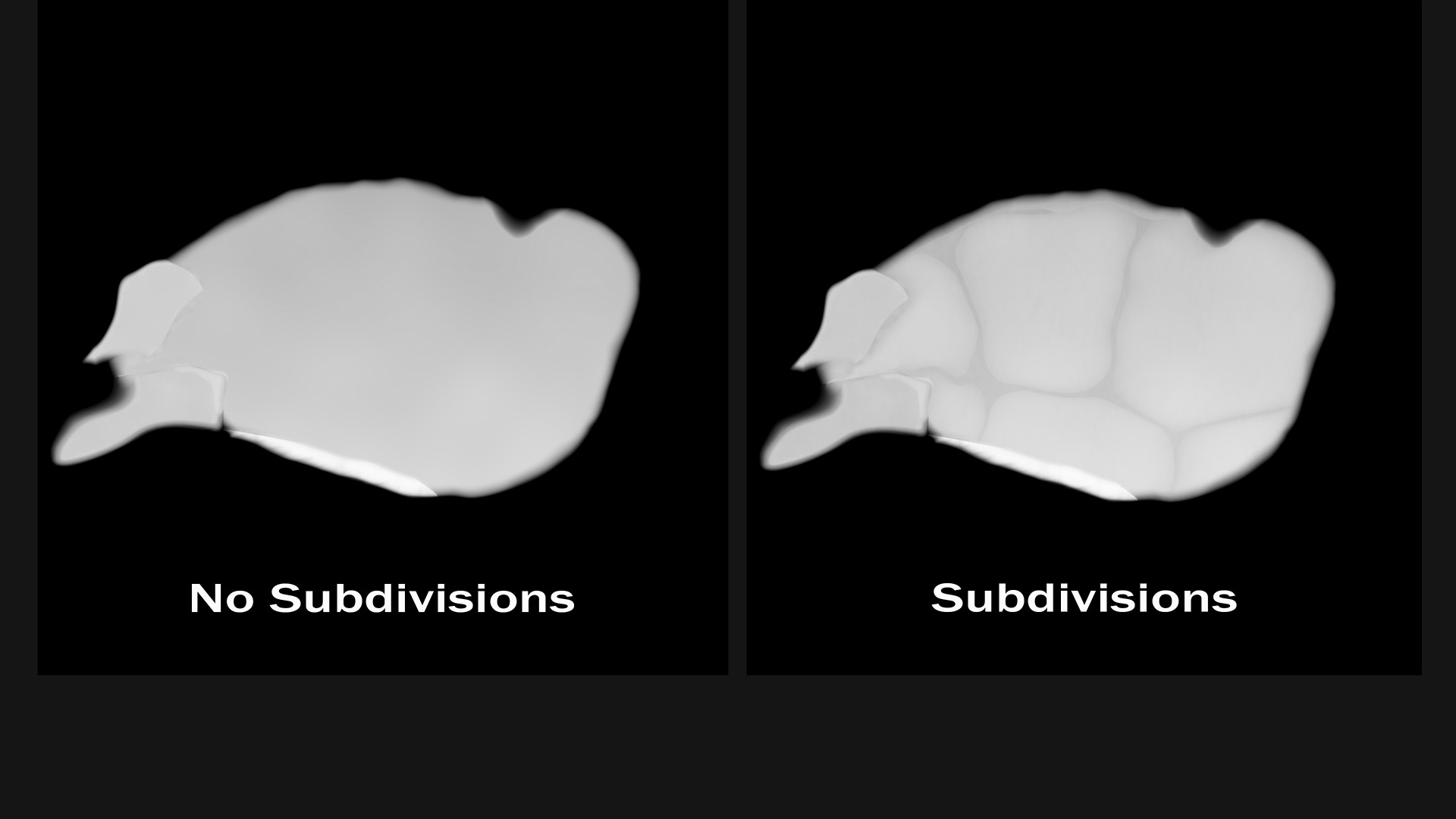
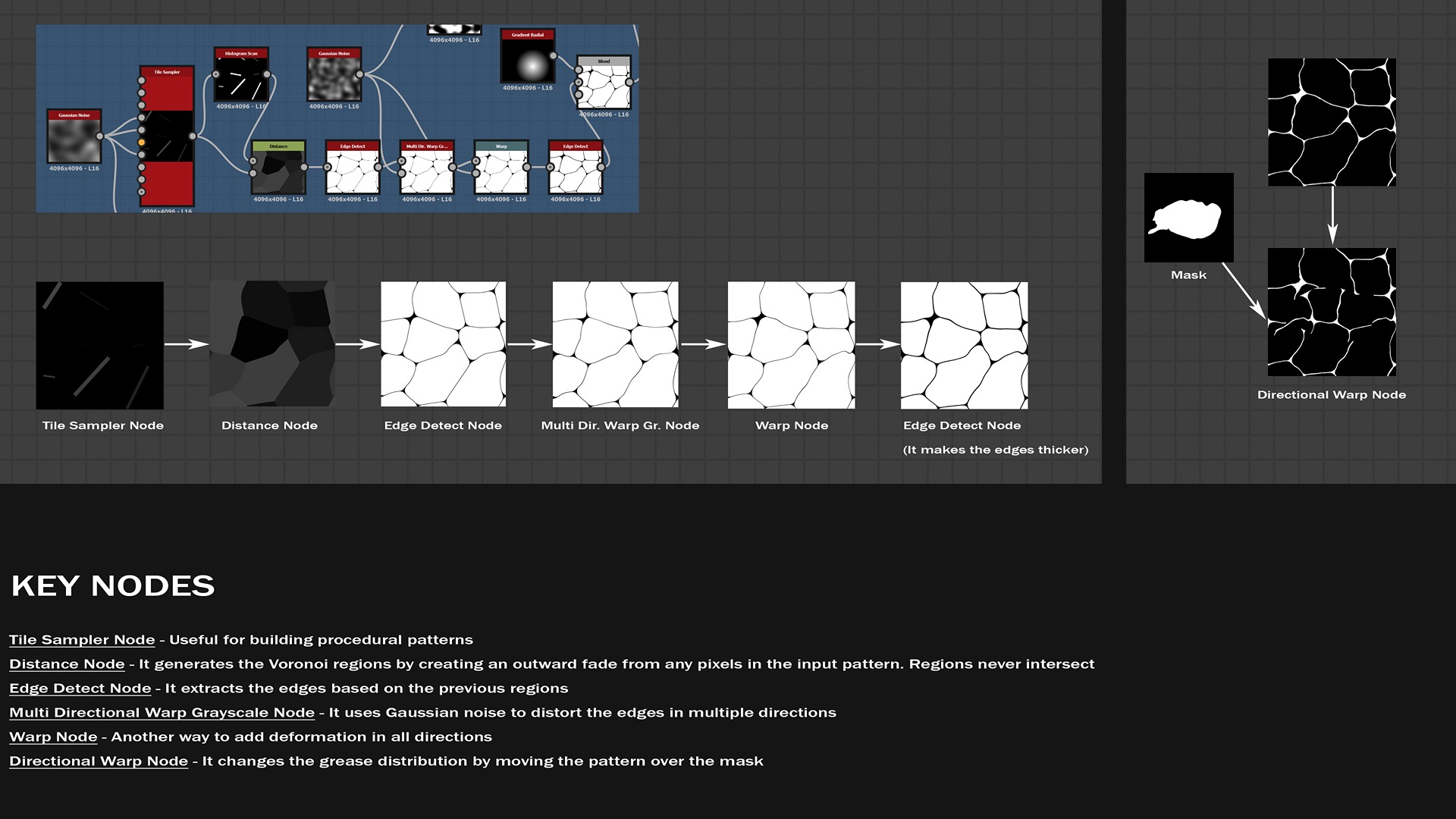
Part of the following graph shows a simple but efficient technique to subdivide the space into regions: it comes from mathematics and is called the Voronoi Diagram.
This method is broadly used for generating rock sediments, but I found it useful in my particular case.
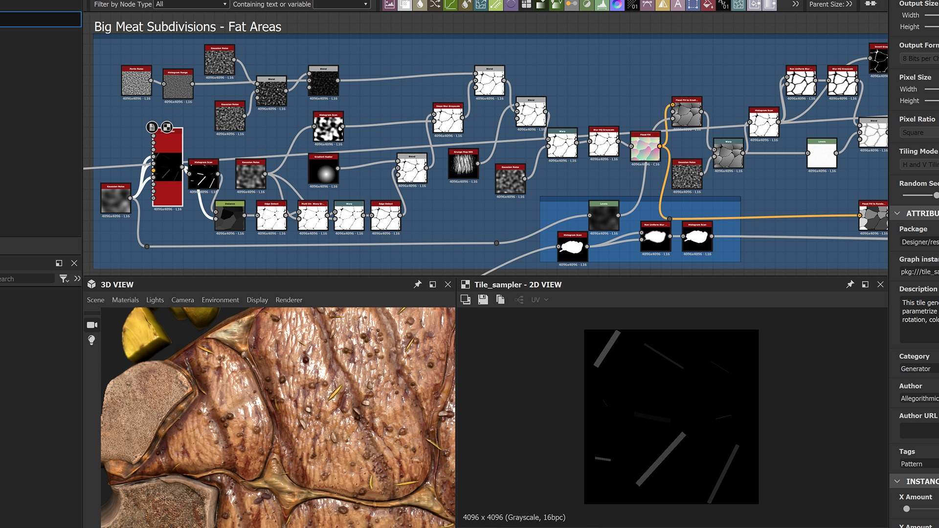
Starting from simple rectangular shapes, I created an outward fade to generate random regions. I then extracted just the edges and applied various deformations.
This step requires patience and many experiments to achieve a compelling subdivision. I used a Directional Warp node to show you the pattern being chosen within the steak area.
Further refinements of the mask were made elsewhere in the graph to eliminate the bone areas and other details from the grease influence.
Finding a way to create a convincing texture for the grease can be challenging.
This subnetwork (red frame) is responsible for adding details to those areas.
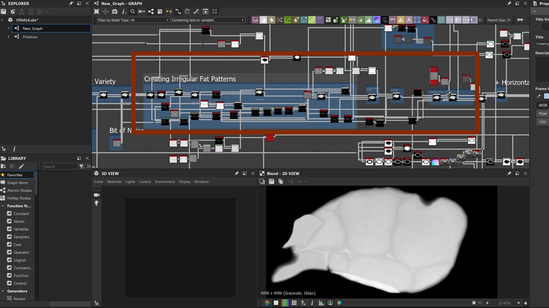
Let’s sum up part of the process involved through the following video. Starting with the grease mask, I applied the Non-Uniform Blur node to it in order to “eat away” part of the input and leave just the larger portions.
The Quantize node introduces banding, which is then blurred and added to the steak.
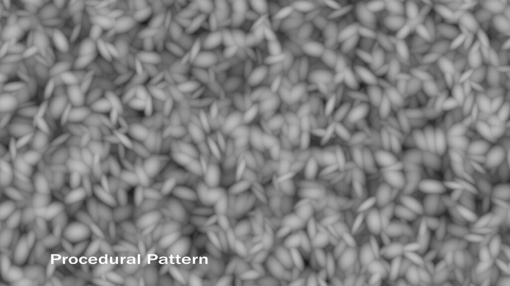
Separately, I created a custom procedural pattern to lay onto the greasy part, adding a bit of variety to the surface.

Meat Texture
A very important subnetwork is responsible for the meat texture.
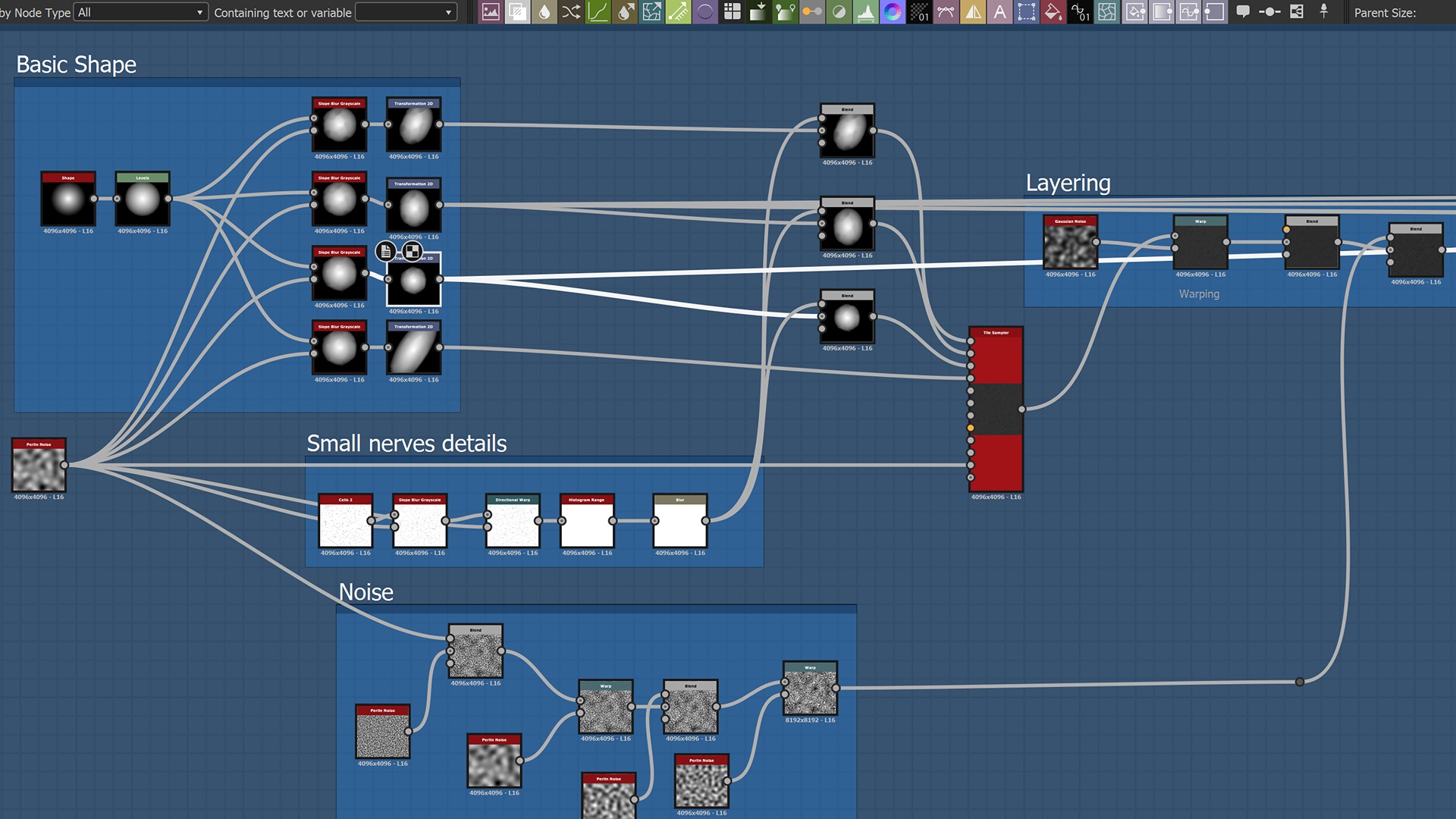
The section called “Basic Shape” starts with a simple cone primitive, from which I created four different non-uniformly scaled versions. I then added some features, referred to as “Small nerve details,” on top of them.
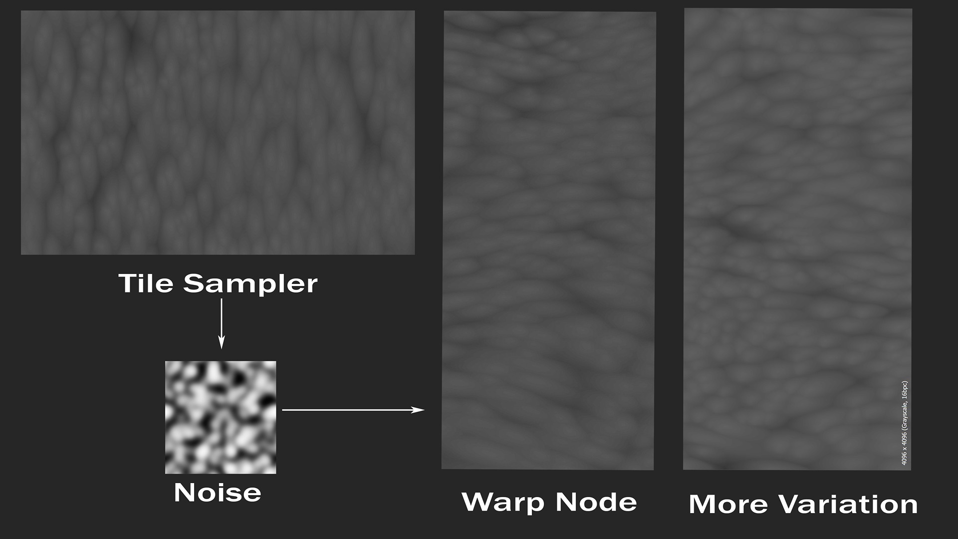
Using the Tile Sampler node, I generated a custom pattern and added custom “Noise” and deformers on top of it in the “Layering” section.
Here is the result of the tile sampler node, followed by the warping effect and other changes to make the pattern more organic.
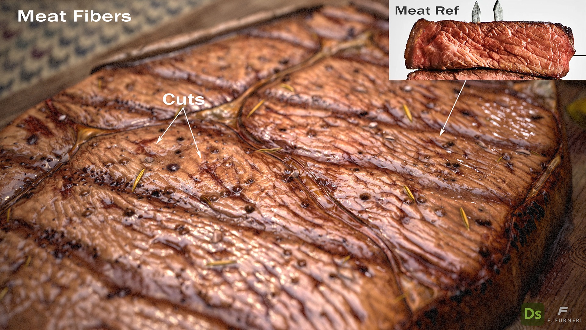
The cuts are generated by inverting the meat pattern (just to obtain brighter pixel values in recessed areas) using Levels and applying a Histogram Scan node to isolate some of the recessed cuts.
The purpose of this is quite obvious: on one side, the cuts are blended over the steak surface to make those areas deeper.
However, they are also used as a mask for adding a reddish color while creating the albedo map.
Here is the subnetwork dealing with the cuts.
If you want to reduce the number of resulting cuts or add more variations, you can apply a black-and-white or grayscale pattern over the cuts using a suitable blending mode (e.g., multiply). The more organic, the better!

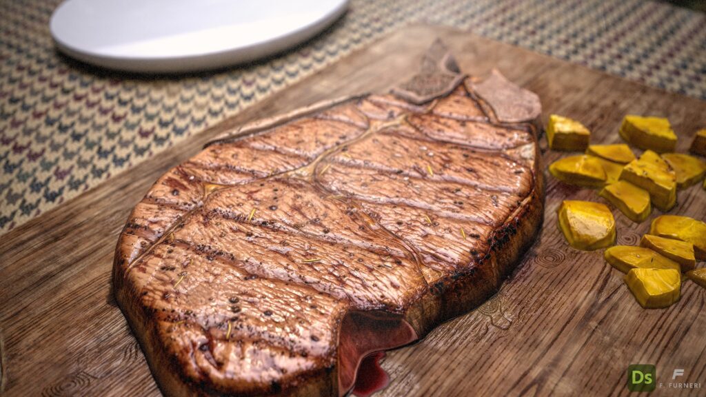
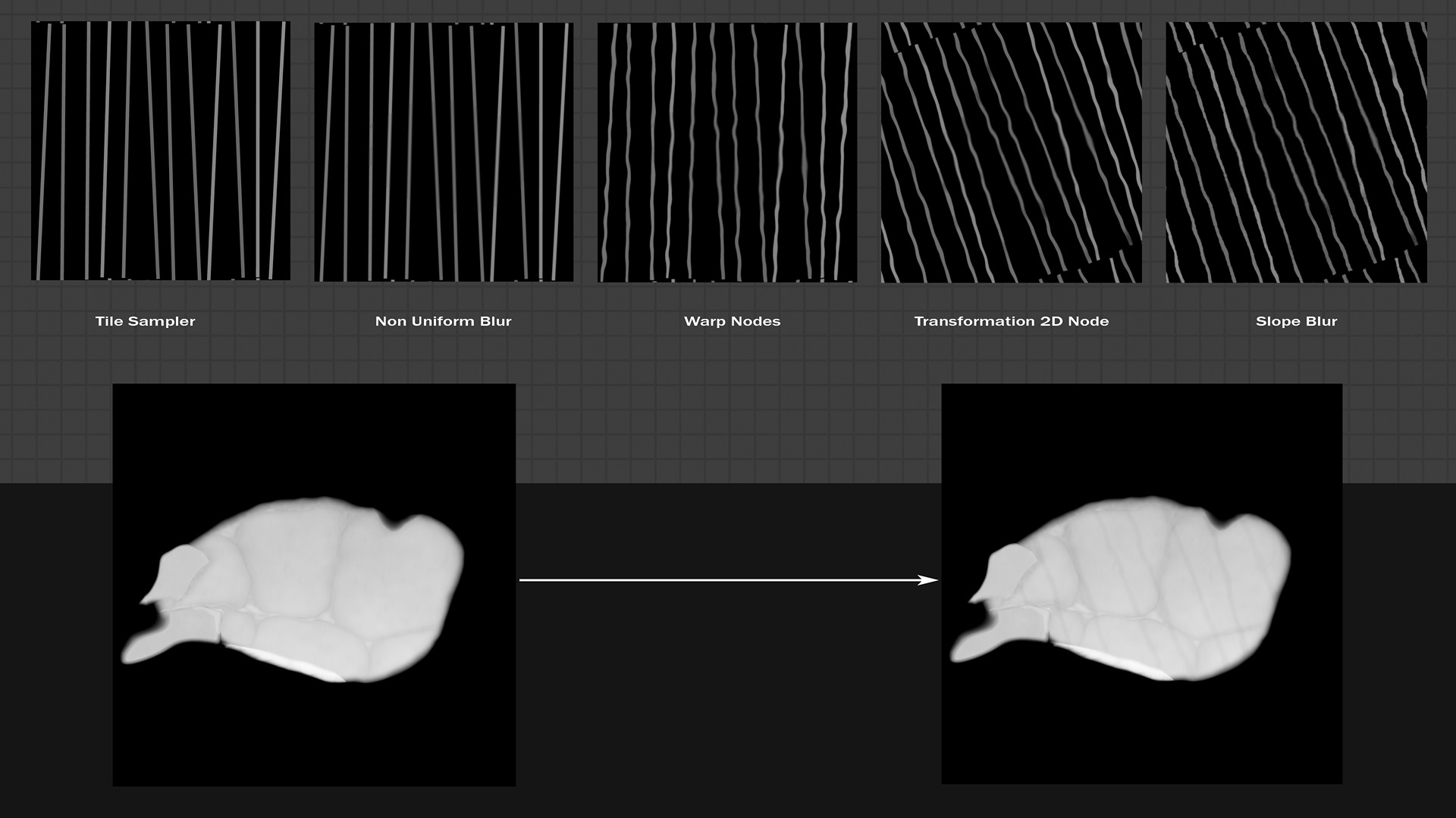
Grill Marks
A juicy grilled steak usually has grill marks on its surface, produced during cooking.
They are located along precise directions: some steaks have marks in multiple directions, forming a crosshatch pattern, while others maintain a single orientation.
I opted for the latter.

Beginning with the Tile Sampler node, I applied the Directional Warp node followed by the Warp node, which allowed me to deform the straight lines.
Additionally, I multiplied the result by a procedural Perlin noise and oriented the lines in a nearly diagonal direction using the Transformation 2D node.
Finally, I added more details using a Slope Blur Grayscale node. The result is then layered onto the steak.
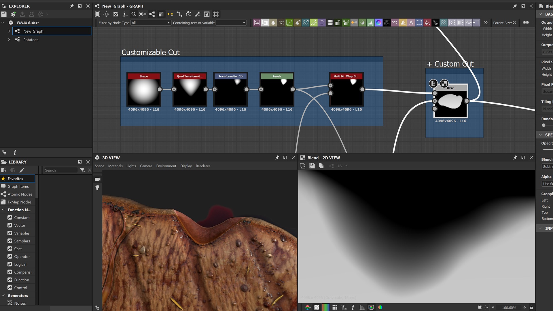
Customizable Cut
With the idea of adding distinctive features, I decided to include a triangular cut at the edge to reveal the steak’s doneness.
I began with a paraboloid and used a Quad Transform node, which is very useful for modeling a shape based on four control points.
A 2D Transformation node allows me to translate the shape as needed, while a Levels node comes in handy for adjusting the histogram: in this case, I adjusted the luminance levels in order to prepare for a proper boolean operation.
Before that step, a Multi-Directional Warp node helps deform the result slightly.
Finally, a Subtract node effectively removes the triangular shape from the steak.
Note: I intentionally started from a paraboloid because of the gradient effect at the edge: the cut doesn’t need to be sharp and vertical but should have a slight slope towards the base.
The Importance of Creating Masks
Masks are crucial when working with materials: for instance, you may want to isolate specific parts without affecting the rest.
As the project grows and the number of nodes increases, it is a good habit to create a specific block that includes the most frequently used masks throughout the project.
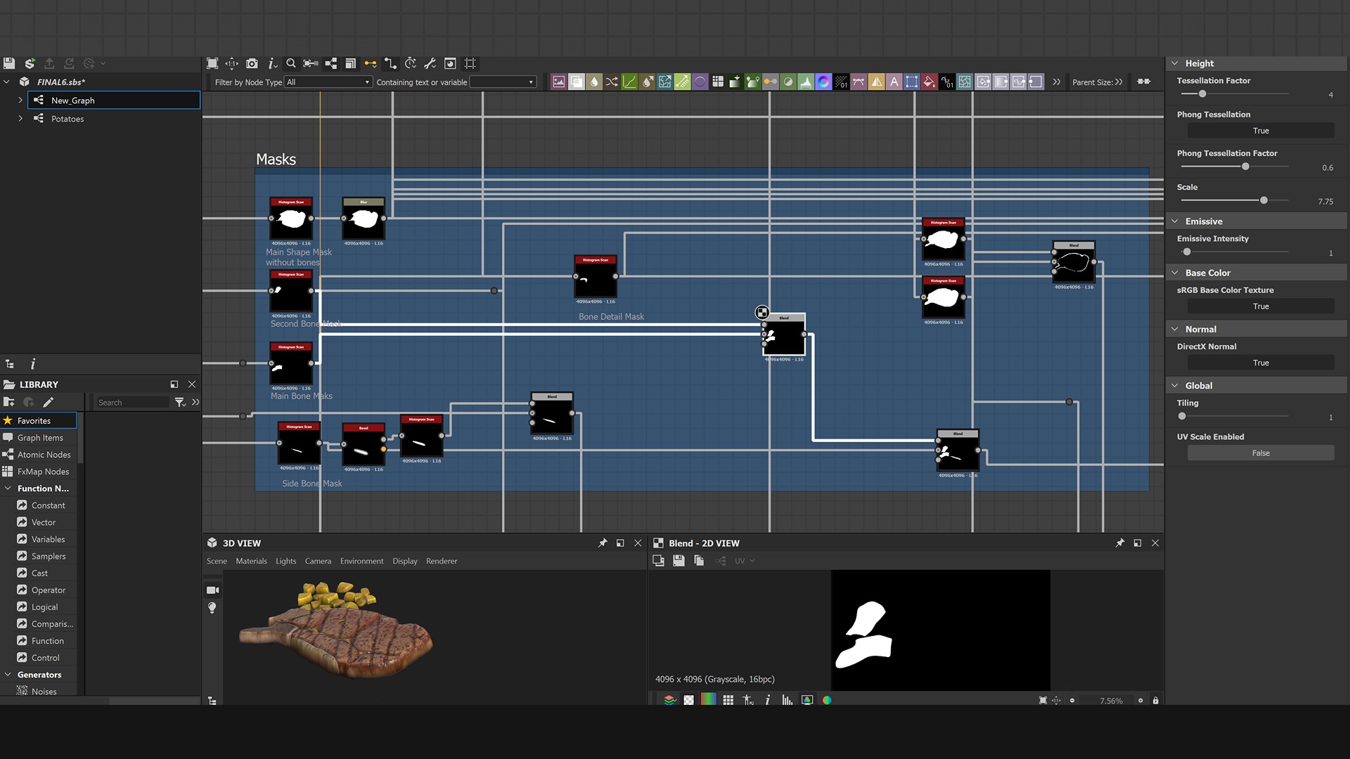
I isolated a few portions of the steak, as black and white textures, and used them primarily during the blending operations for the albedo, height, and roughness maps, among others.
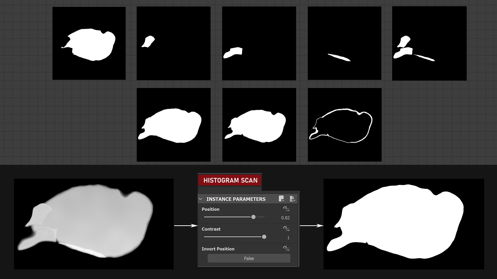
An easy way to create masks in Designer is via the Histogram Scan node: by taking the maps with details as input and tweaking the position and contrast parameters, you can customize your own mask.
It is then ready to be used with blending nodes.
Polish and Additional Details
When the main shape is established, it is time to add more details to the base and refine textures and surface imperfections.
At this stage, if your material doesn’t look solid enough for adding further details, take a step back and work more on your graph. Otherwise, you are ready to proceed!
But what kind of further details do we need?
- Burnt spots
- Salt
- Spices
- Potatoes
Burnt spots can result from either the grill itself or high heat, which causes sugars and proteins to caramelize and create dark or brown areas. These spots are typically distributed throughout the steak, with some areas often found where the grill marks are.
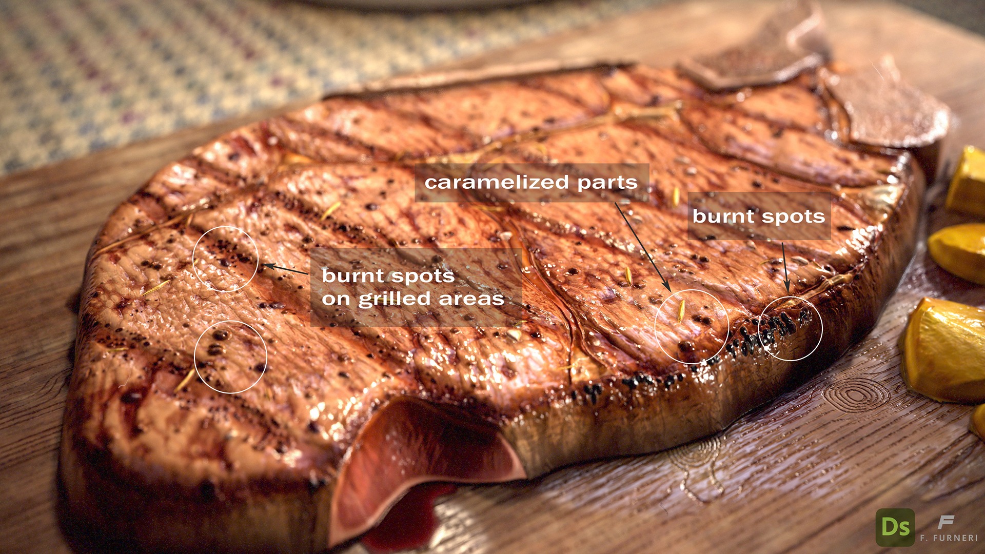
One of the main challenges here is to manage a good variety of dots of different sizes: some are bigger, others are smaller and have different concentrations.
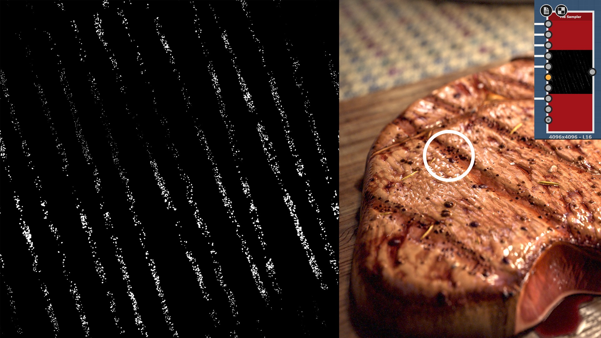
When adding scattered elements layered on top of each other, a Tile Sampler node is very efficient.
Besides its wide variety of built-in parameters, it allows the connection of several maps for better control over the placement of scattered elements.
The black spots in the grilled area use a specific mask map to limit the scattering within the appropriate region.
To increase the variety of the elements, a good practice is to build around 4 or 5 different types of spots to connect to the Tile Sampler node inputs.
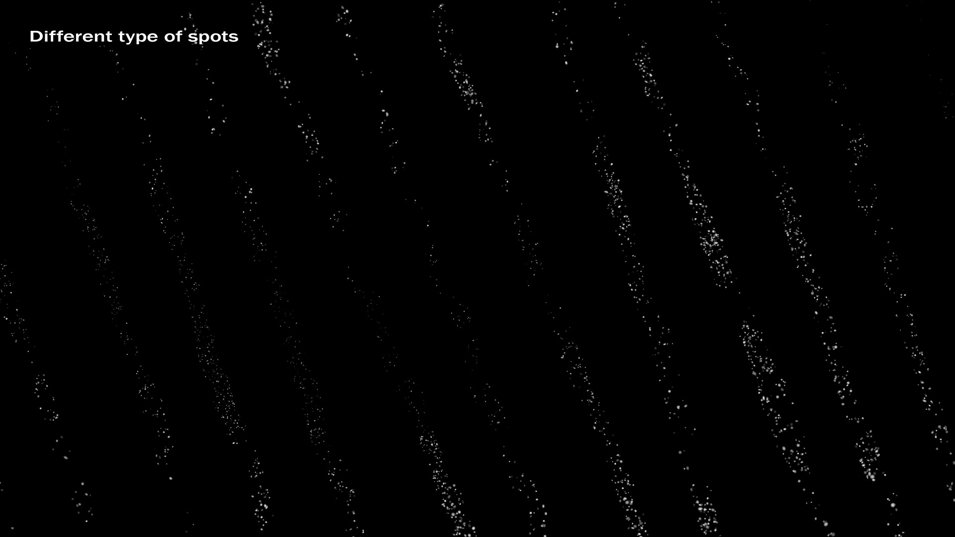
Depending on the result you want to achieve, there is also a parameter called Position Random in the Tile Sampler node, which shifts the spots to different areas:
I generally keep this value quite low to avoid intersections, but in this case, you could experiment with a bit of overlay for a more organic look.
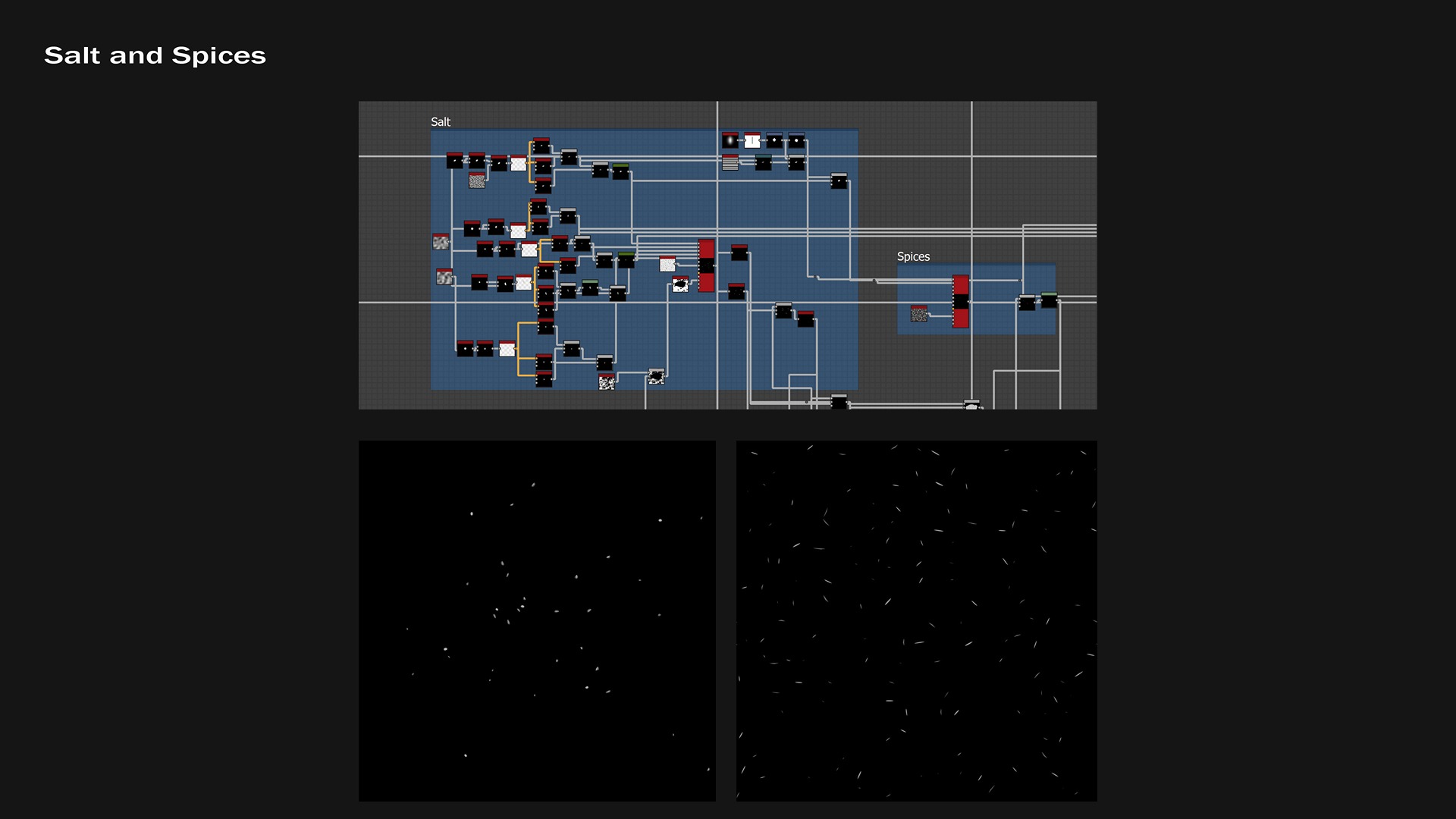
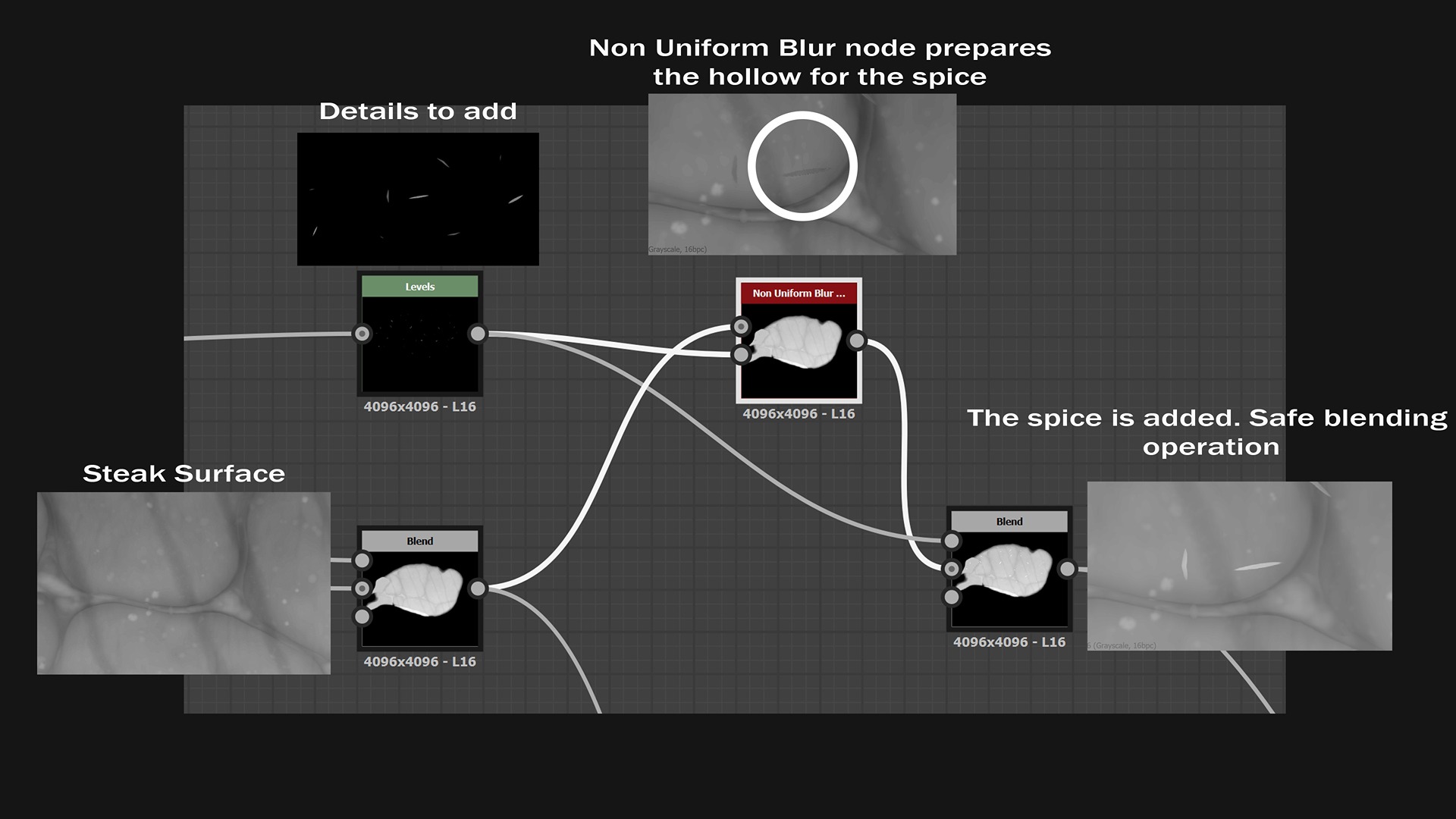
Salt and spices use the same principle as the spots, but with different input maps connected to the Tile Sampler node. This allows for customization of the elements’ rotation, scaling, distribution, and more.
A common issue you might encounter while scattering elements is a dirty overlay. This typically happens when multiple objects from different layers occupy the same position in space, resulting in poor blending if not properly addressed and refined.
I’ve learned a practical and quick workaround, involving two nodes: Non-Uniform Blur and the Add Blending Mode, as illustrated in the following figure:
Perfecting Details on Steak’s Border
The previous techniques involving the scattered elements work well on the steak surface, but what about details on borders?
We must be aware that we are not sculpting directly on a polygonal model; instead, we are designing a 2D heightmap, which essentially displaces the vertices when applied to a surface (we’ll see how the steak is extruded from a flat plane later).
If we don’t account for this and simply apply procedural maps as they are, the elements on the borders, with a relevant slope, might appear stretched.
Let’s explain that by an image:
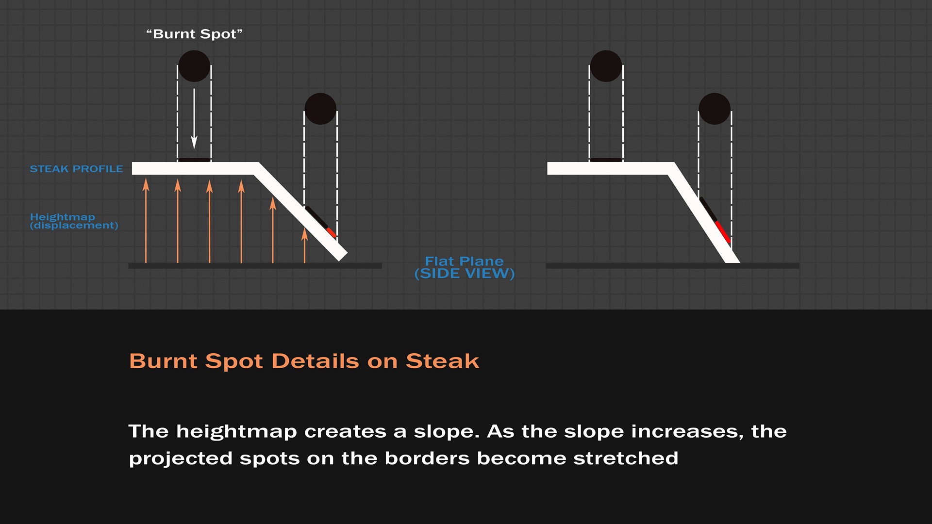
That’s an explanation from the side view, but the map we build is from the top view, just like all the textures, but the logic doesn’t change at all.
Depending on how you have built your procedural texture map, you might have both thick and thin borders.
Here, the ambient occlusion map is used intentionally to illustrate how the borders are not completely vertical. This provided me with the opportunity to add details there.

Therefore, there are no strict rules when dealing with details on sloped surfaces: I usually test the degree of stretchiness of the details first, then decide how much to reduce it.
A practical solution is to introduce a Transformation 2D node for the details, using vertical or horizontal non-uniform scaling — the steeper the slope of the border, the more scaling in one direction is needed.
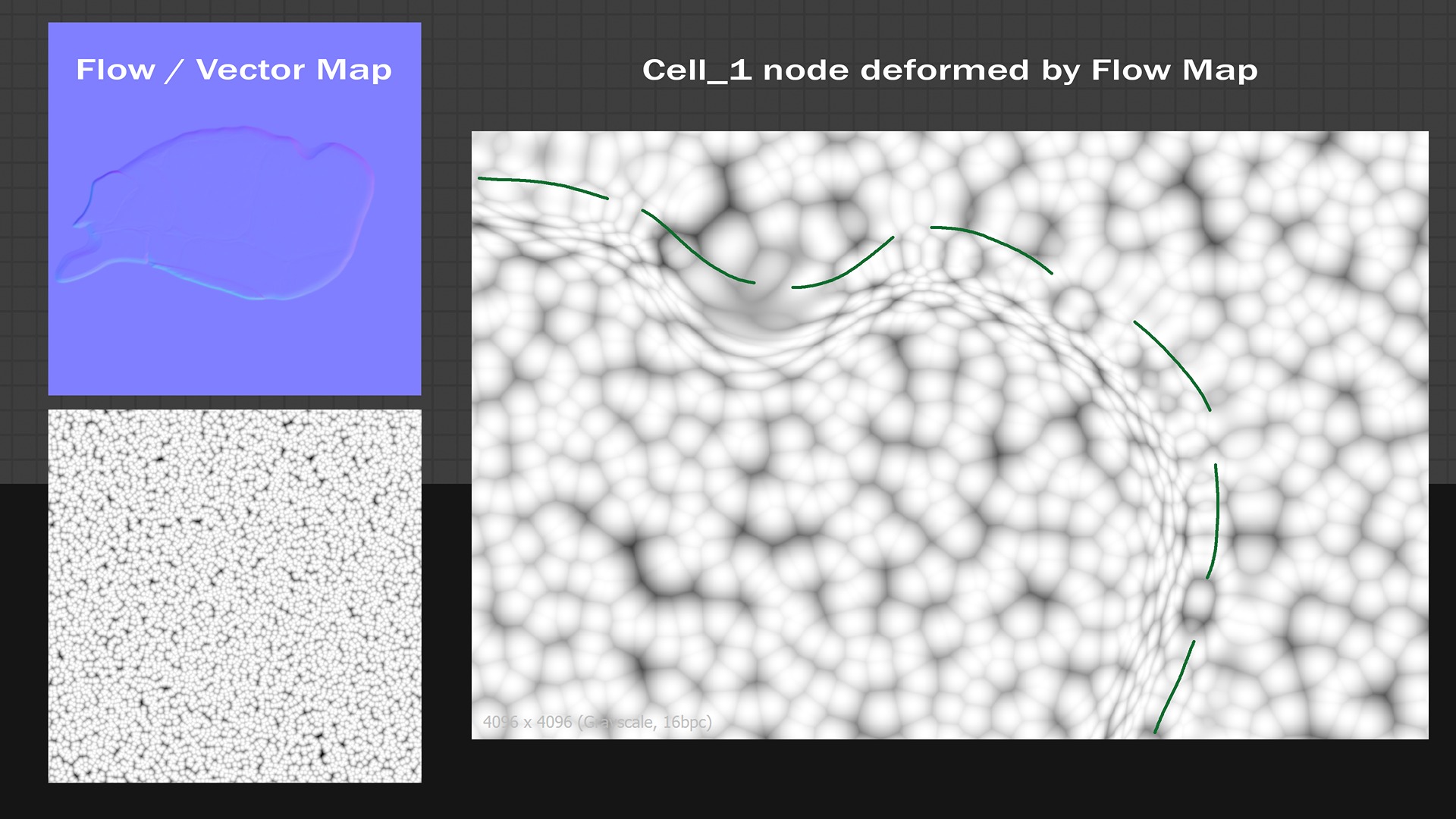
Another technique that helped me create a natural detail flow along the borders lies in an operator called the Vector Warp Grayscale node:
In this example, a normal map (called Flow / Vector Map), and generated from a cube shape, deforms a Cell_1 procedural node in a way that the cells follow the cube’s contours.
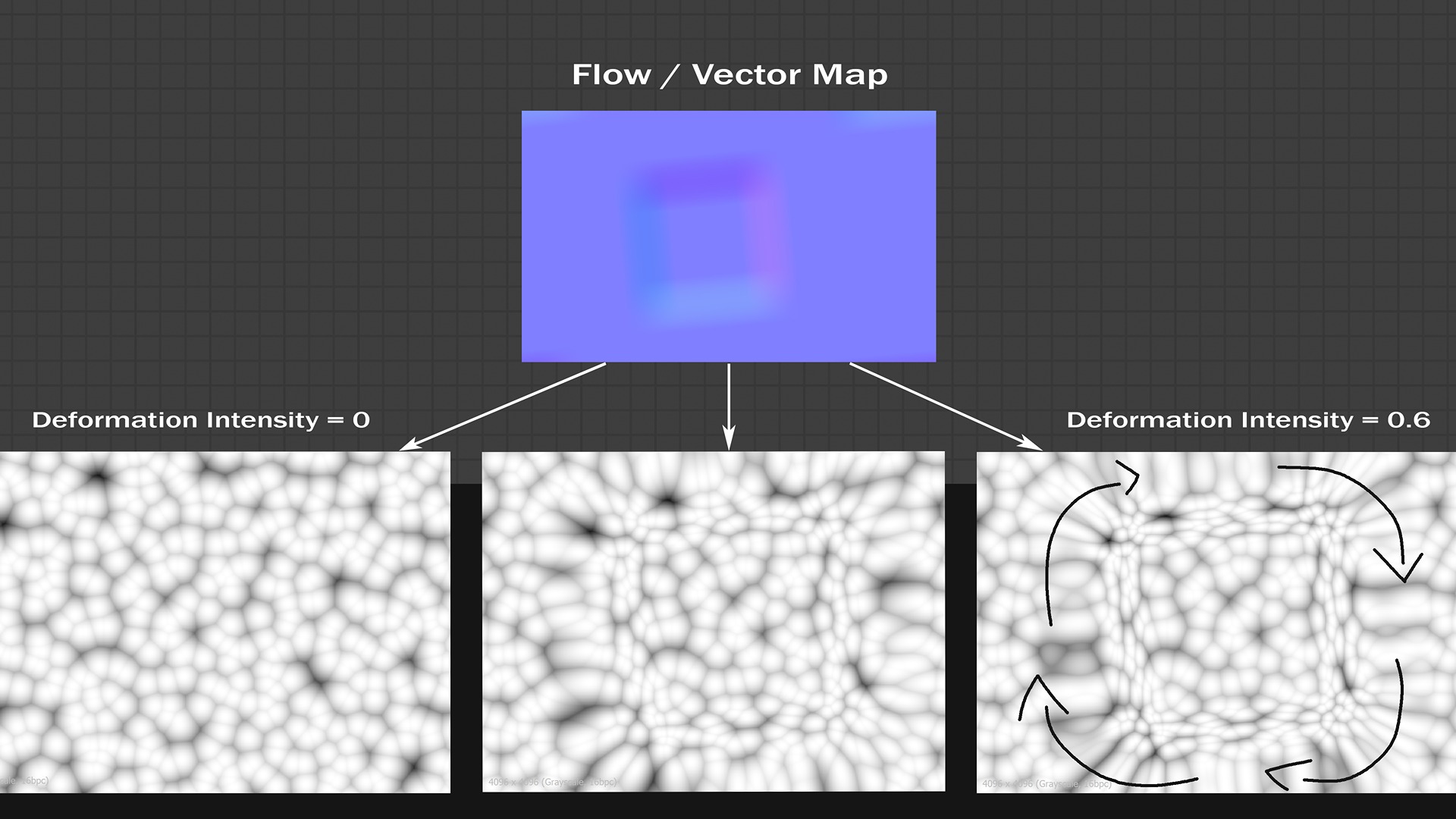
With the same logic in mind, the normal map that describes the steak’s contour deforms the burnt spots and details, making them follow the steak’s curvature.
This is just an example using a Cell_1 node as the starting point. From there, you can refine the result, reduce stretching effects, create random shapes, and use various blending modes to achieve a unique border, which is exactly where I started.
Blurring Jagged Edges
When you explore Designer, there are a multitude of nodes available out of the box.
Some of them perform warping effects, but some others might sometimes lead to unwanted results that need to be polished.
Let’s consider the Quantize node, for instance, which creates discrete areas based on an input gradient map: because of its nature, the transition from one zone to another introduces some aliasing.
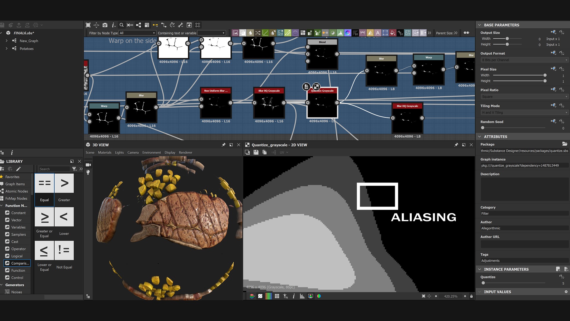
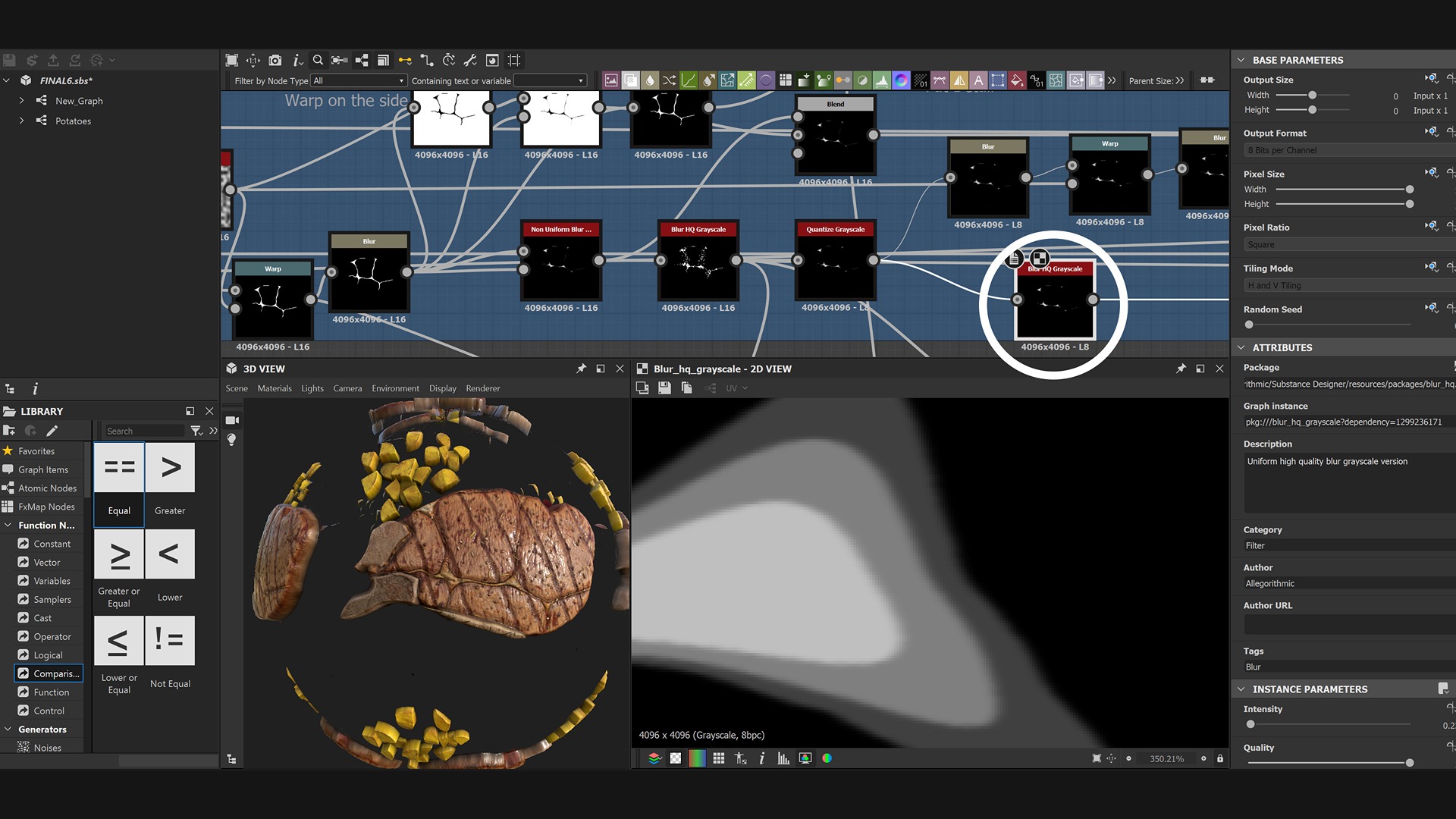
Moreover, when the node is connected to other nodes and the graph gets complex, you risk propagating the aliasing effect and may have difficulties discovering the procedural node which has generated it: the Blur HD Grayscale node comes to the rescue!
In the example, I used it right after applying the Quantize node, which made the result much blurrier but allowed the discrete areas to be blended more effectively.
Adding Soft Noise Overall
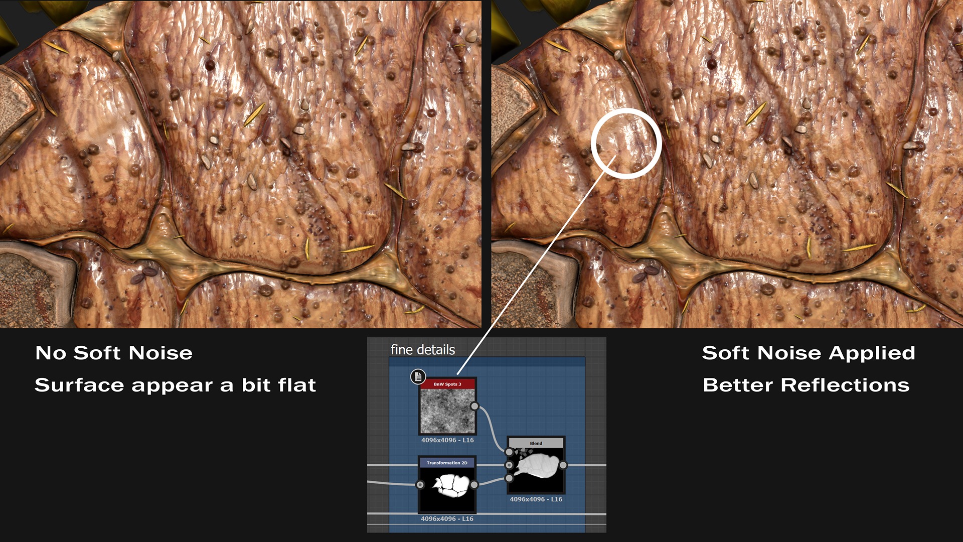
As the cherry on top, consider adding some light procedural noise to the steak’s surface. While this is not mandatory, I found it beneficial for two reasons:
- It helps create a more interesting roughness map for reflections
- It makes the steak appear more realistic by introducing macro and micro imperfections to the meat fibers.
This is from the Substance Designer preview, but it clearly shows the effect of the BnW Spots 3 node overlaid.
Maps
The height map is one of the various PBR maps that need to be generated; it includes all the displaced details from a flat surface.
This quick video shows a few steps involved in the creation of the height map.
Albedo
Additionally, there is the albedo map, which contains the color information. Let’s take a closer look at it.
When I approach texturing, I typically begin with a uniform base tint and gradually build color variations on top of it. Also, blending modes help me mix the layers with ease.
Here is my general workflow:
- I prepare and combine several grayscale “utility maps” which contain the primary features to consider for the texturing process.
- I remap these grayscale inputs to color ramps using the Gradient Map node.
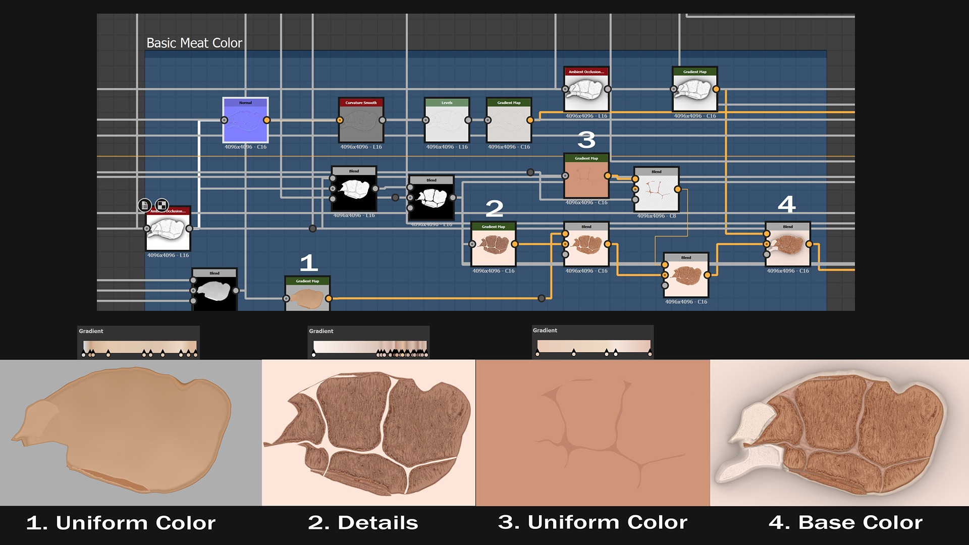
- I employ various blending modes to merge the color maps and create custom masks where necessary.
Color Variations
By introducing breakage, we can avoid a too-perfect look. To accomplish this, I mainly rely on Grunge Maps.
Unlike curvature or ambient occlusion, these maps aren’t directly tied to the steak’s features.
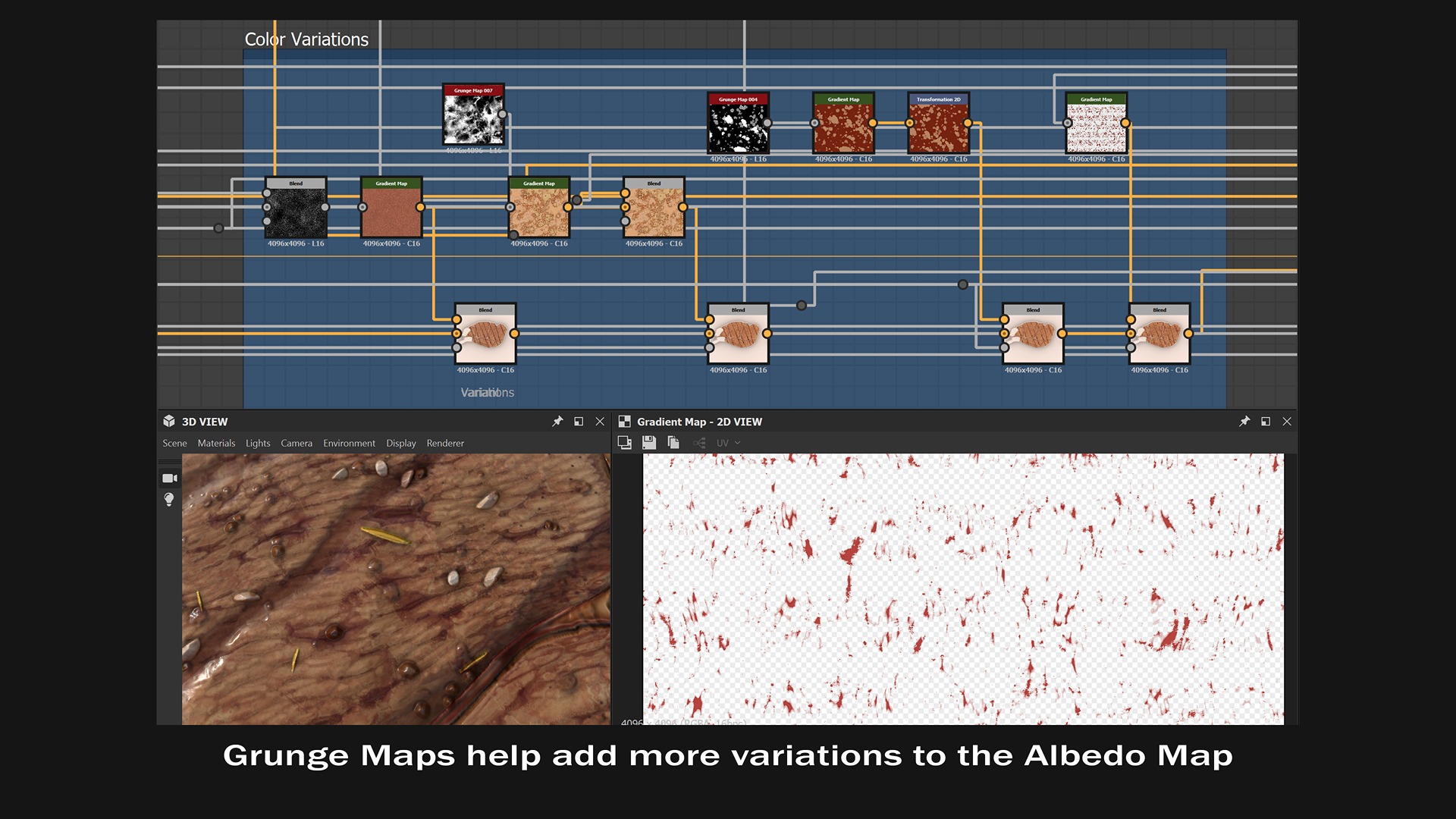
However, grunge and noise maps are incredibly powerful, especially when striving for a more natural look.
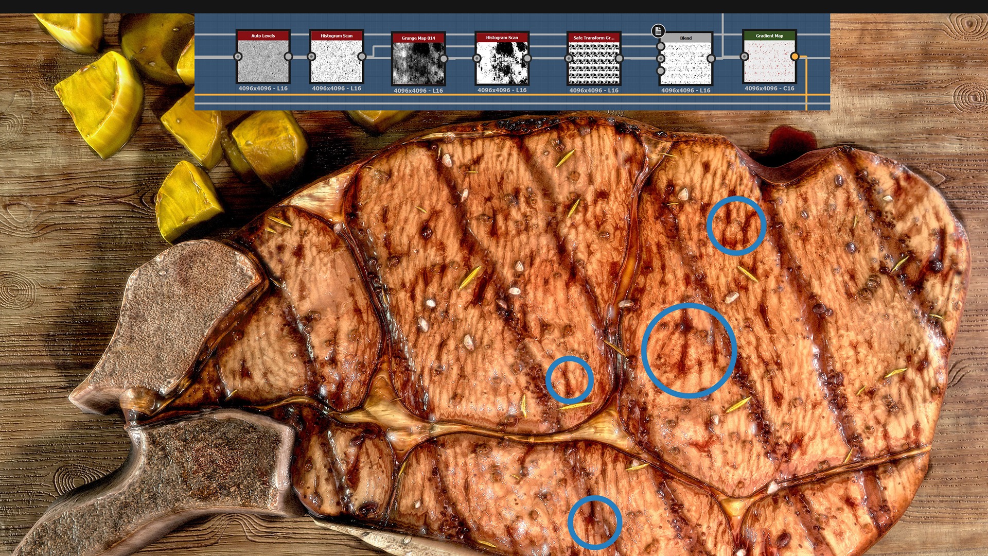
On the other hand, cuts are typically found in recessed areas that correspond to the steak’s finer details.
I start with a grayscale map of the meat fibers and apply a Histogram Scan node to isolate the sunken parts. Then, I use Grunge maps to selectively erase random portions, followed by a Gradient Map node to apply color.
This approach ensures that I don’t add reddish color to unwanted regions.
A similar method applies to the bone textures. However, instead of starting with the heightmap, this time we choose the Ambient Occlusion and develop the color details accordingly.
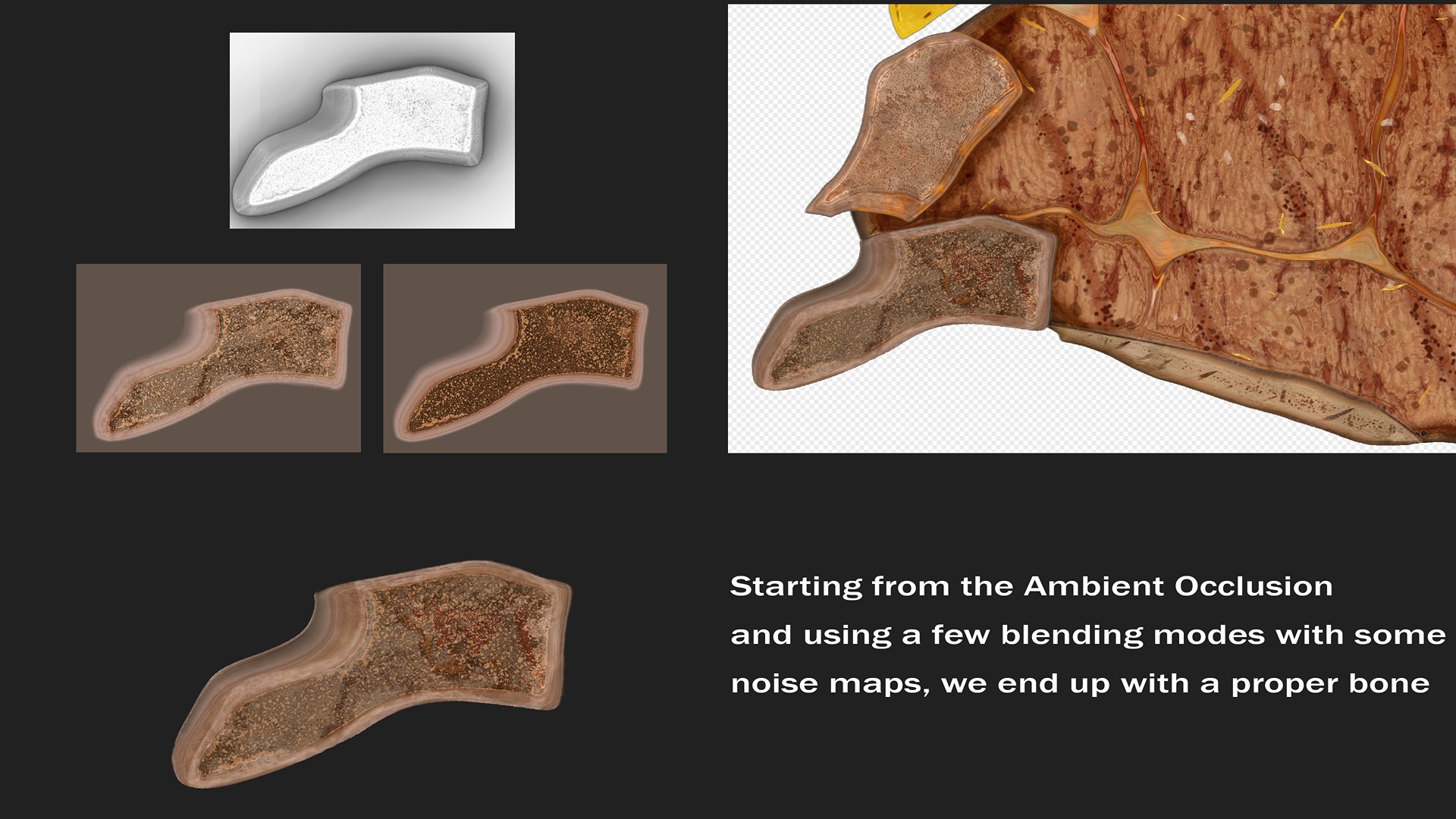
Blood Stain
Building this feature is quite simple and straightforward, as well as texturing it.
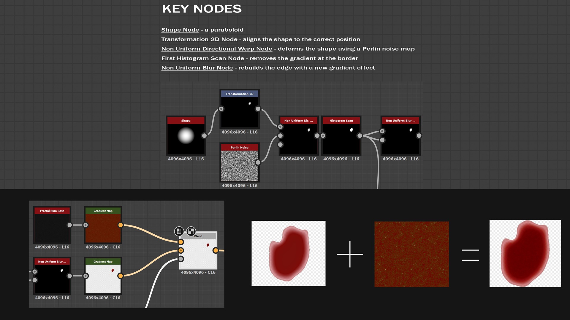
The inclusion of this feature makes the overall result more organic and visually engaging.
I intentionally excluded the blood stain details from other PBR maps, such as normal and ambient occlusion, because I wanted a flat appearance without soft shadows.
Potatoes
Texturing this part involves adding color variations to the main surface, along with incorporating additional details such as rosemary, salt, and some burnt areas.
The approach is similar to the previous techniques, so I will simply show some of the intermediate textures.
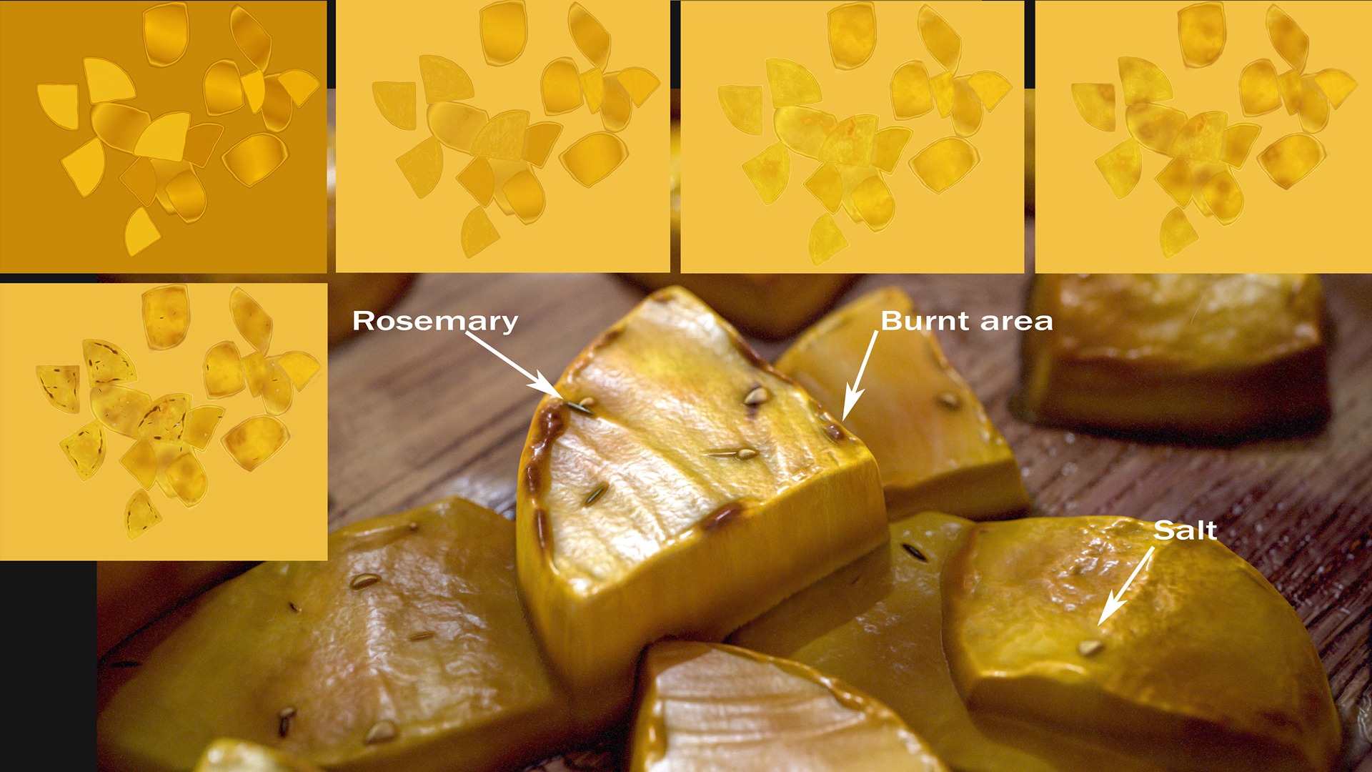
A word of advice: in general, when creating the albedo, pay close attention to the subtle color variations in your references, even if the surface initially appears uniform.
The key to achieving realism lies in replicating those small tint differences. Additionally, avoid fixating on your references for too long; take breaks and revisit them with fresh eyes—attention to detail often comes from a refreshed perspective.
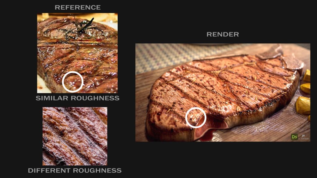
Roughness
While designing the Roughness Map, it’s common practice to start with a few utility maps, just as we did for the albedo.
Roughness on steaks is influenced by several factors, including the meat’s doneness, the presence of burnt areas, more well-cooked sections, or simply some oil applied after cooking. There are no strict rules for designing it—just a keen eye for detail and plenty of patience!
The photo reference at the top has a roughness similar to the render, while the one at the bottom looks slightly blurrier, giving the steak a somewhat dry look.

Other Maps
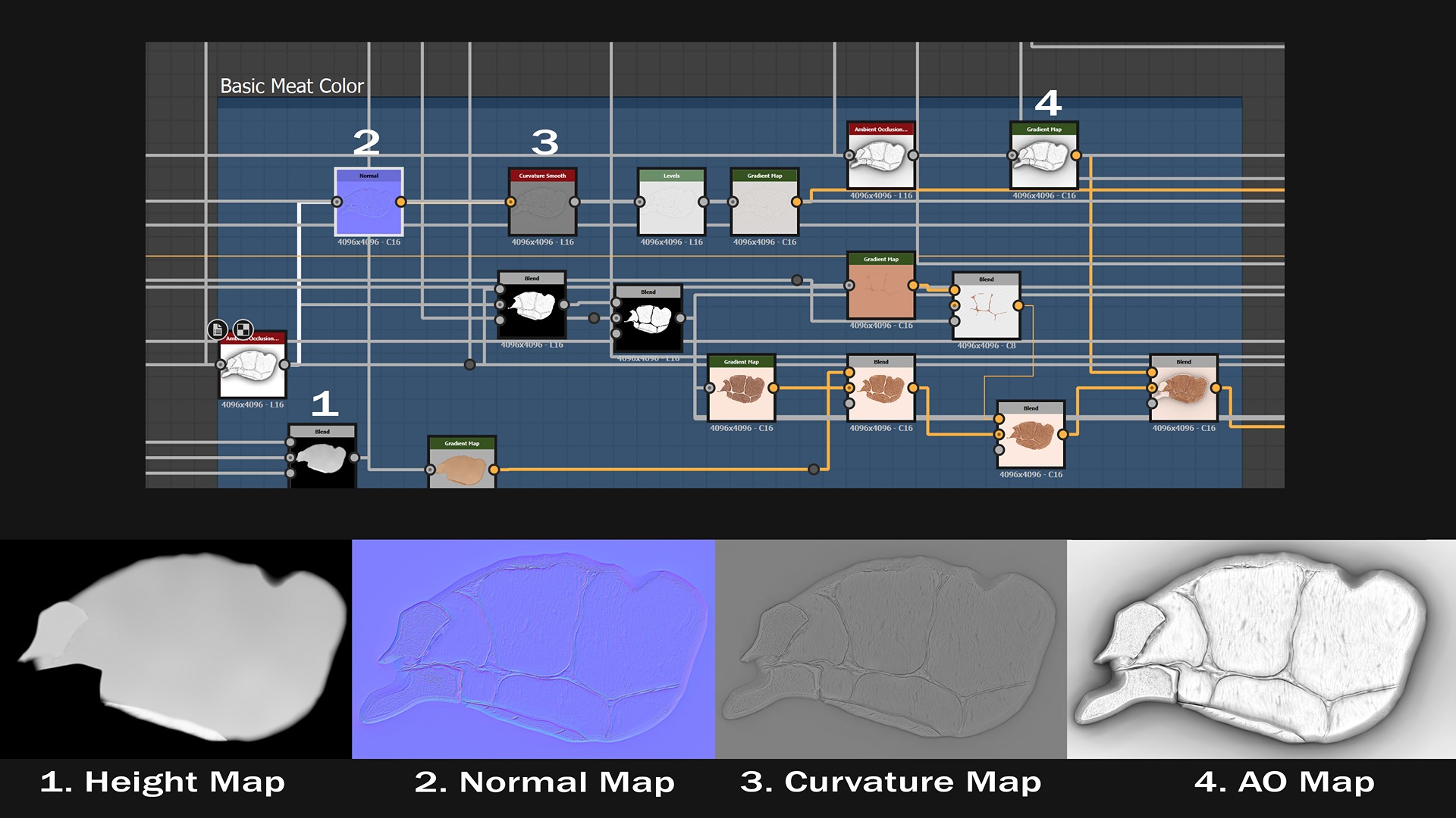
Apart from height, albedo, and roughness maps, there are additional maps that will be very useful during rendering.
In Substance Designer, creating the Normal and Ambient Occlusion maps is quick and straightforward.
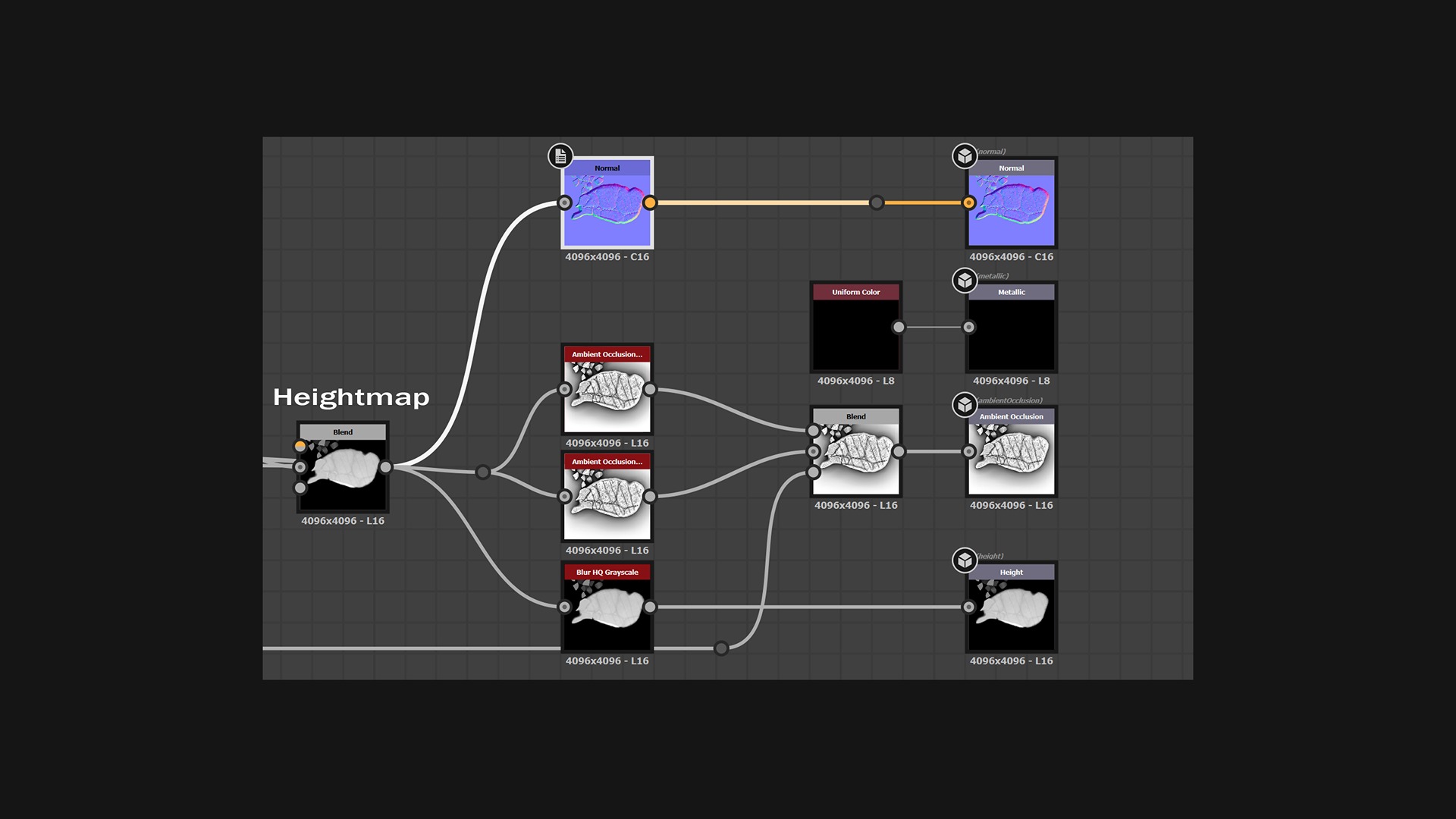
By connecting the height map to the Normal and AO nodes, you automatically generate the required maps.
However, adjusting certain parameters allows for finer control over the quality and appearance of these maps.
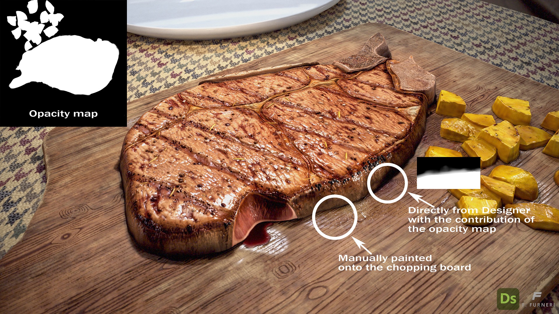
While the Metallic Map is naturally black due to its absence, I considered adding an Opacity Map around the borders. This map is intended to enhance the realism of the integration between the steak and the contact surface.
Later, we’ll further improve this connection by adding custom wet areas directly painted onto the chopping board.
The next image shows an example of two different methods for designing wet and oily parts in the scene.
Lighting and Rendering
When it comes to preparing the final shots, there are numerous options readily available. One of them is certainly Marmoset Toolbag 4, which has grown over the years by offering an advanced ray-tracing algorithm and a huge variety of tools—not just for rendering!
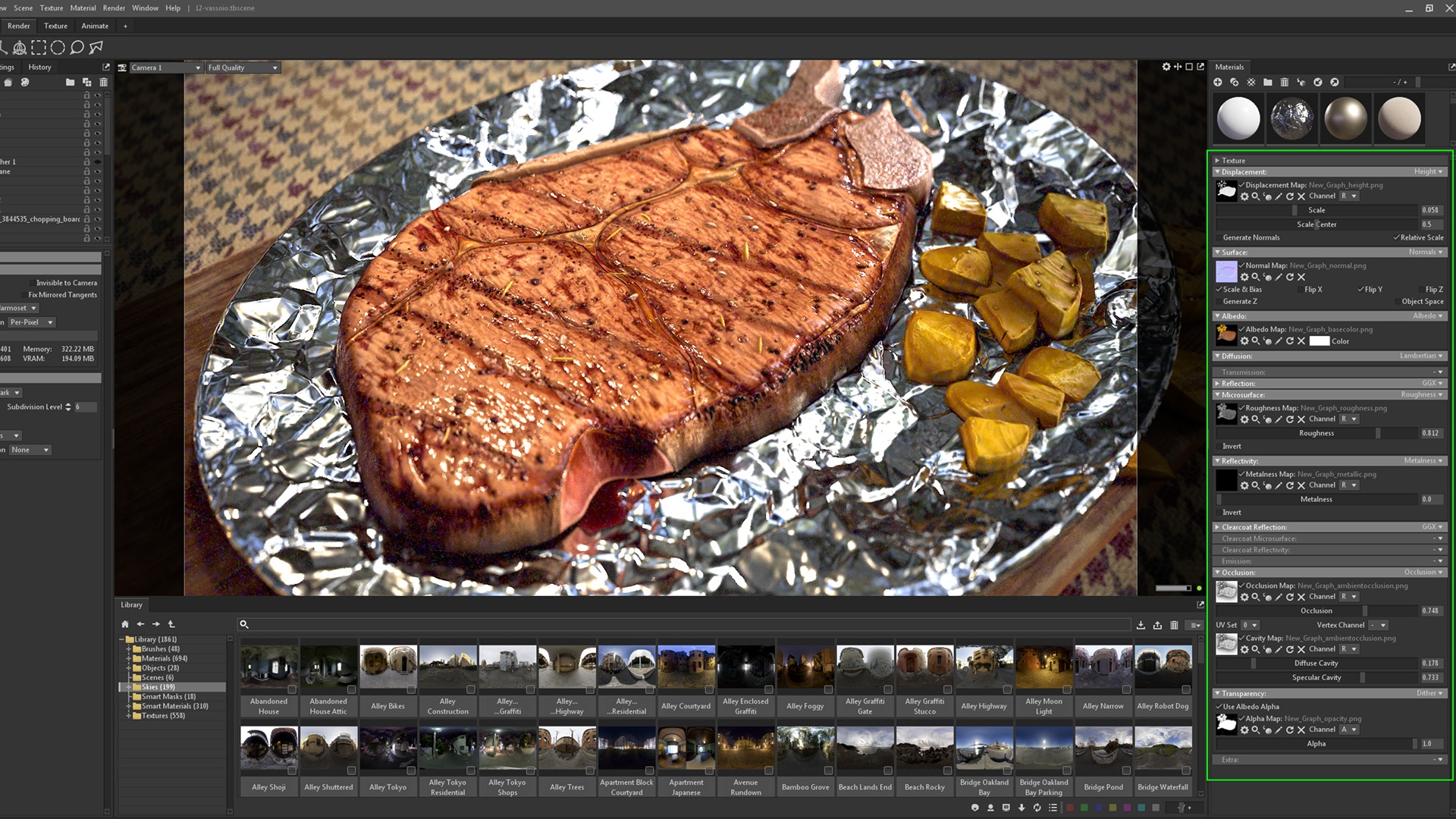
Material Setup
I typically use standard materials in Toolbag with the maps exported from Designer. Here is my main setup:
- Height Map used as the Displacement Map
- Normal Map
- Albedo Map
- Roughness Map
- Metalness Map, set to black in this case
- Occlusion Map
- Cavity Map, created from a copy of the ambient occlusion map to enhance contrast and detail in concave areas
- Transparency, which utilizes the opacity map to isolate the steak and provide semi-transparent details at the edges
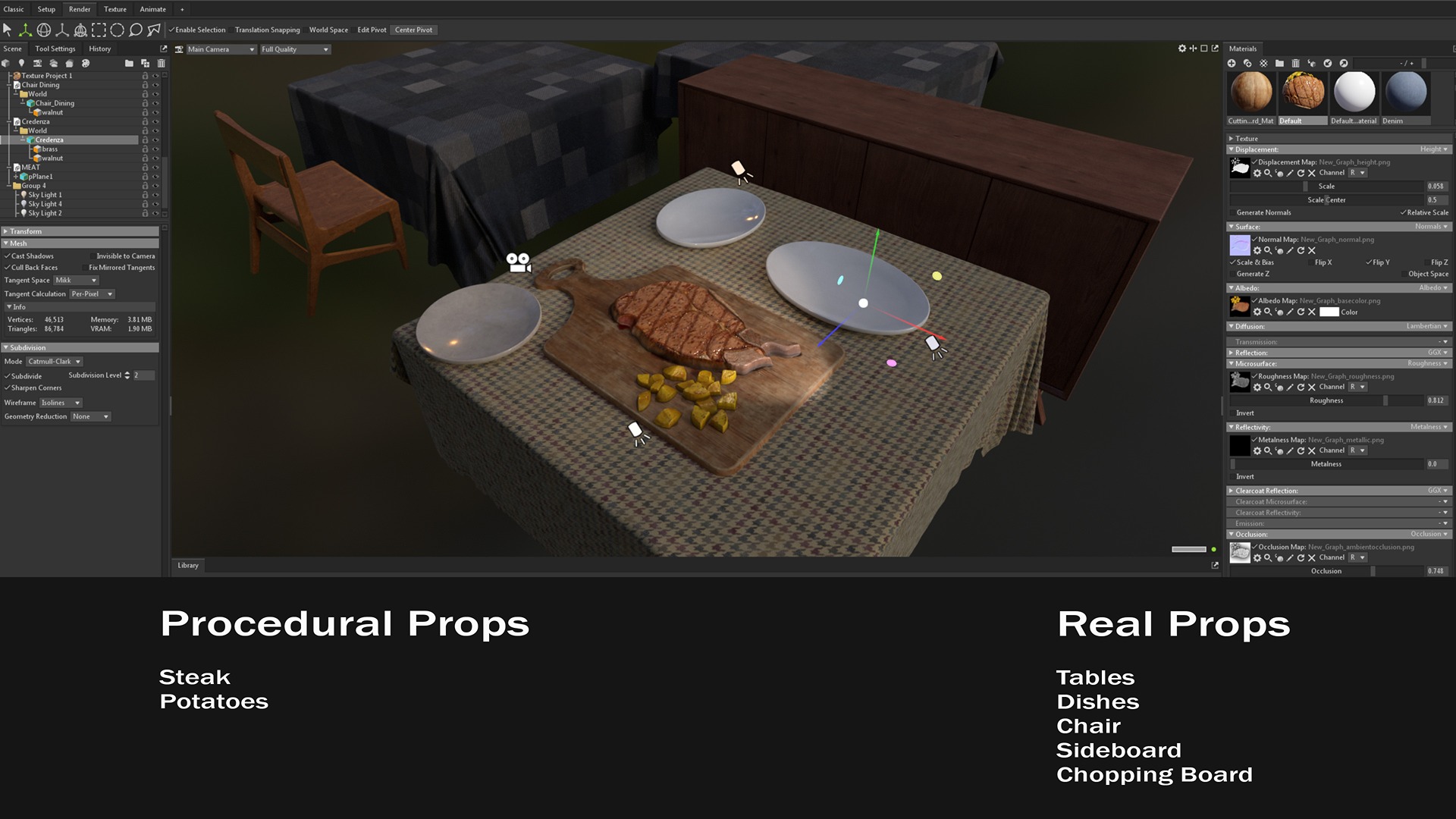
Scene Setup
The steak and potatoes are fully procedural, while the rest of the scene consists of 3D props.
Although I could have rendered the steak on its own, I chose to integrate the hero steak into a simple environment for added context and realism.
The procedural steak is essentially a plane with details extruded from the Height Map.
This flat surface facilitates precise positioning of the steak. If you need to match a contact surface with curvature, you can use deformers to adjust the plane accordingly.
This short video shows how simple it is to set up the plane with extrusion.
Lighting Setup
To showcase my steak, I produced several renders with different lighting setups. Here, I’ll present just one configuration.
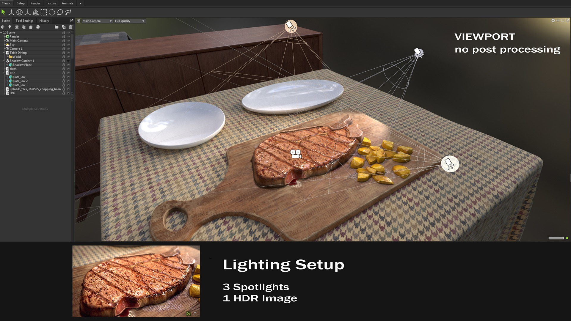
Marmoset Toolbag is powerful in terms of lighting and rendering: it allows you to choose from a wide library of HDR images and add directional lights interactively.
For this setup, I used 3 custom Spotlights and 1 HDR image:
- Top Light: This light has a warm tint, enhancing the vibrancy of the meat fibers and highlighting the grill marks with more specular reflections.
- Top-Right Light: This light functions as a fill light, accentuating the bones and adding interest to the out-of-focus areas.
- Bottom Light: This serves as a fill light for the side of the steak, revealing additional details, including the raw meat visible due to the cut.
Here is a short clip demonstrating the gradual addition of the lights mentioned above.
Rendering
All of the rendered images you see were produced using the Ray tracing feature in Marmoset Toolbag 4. This allows for efficient management of multiple light bounces, providing greater precision in shadows, reflections, and caustics, and delivering exceptional global illumination results.
In addition to these core features, various post-processing settings also play a crucial role in enhancing the final image quality. Let’s explore the specific effects I applied to the steak:
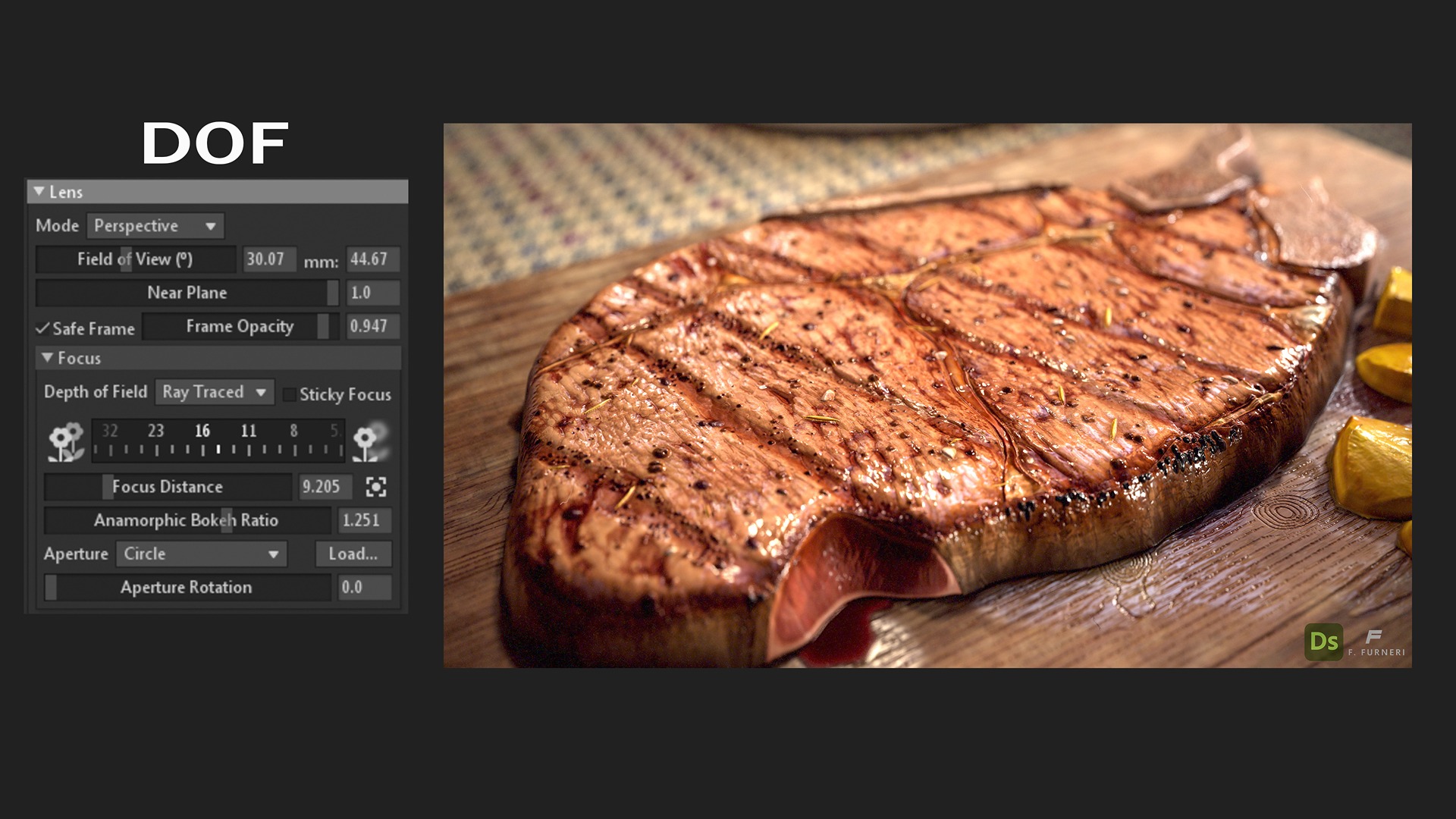
- DOF (Depth of Field): In the lens section of the current camera, I can adjust the focus distance and control the quality of the out-of-focus area. In this setup, the out-of-focus regions are located in the top-right and bottom-left corners.
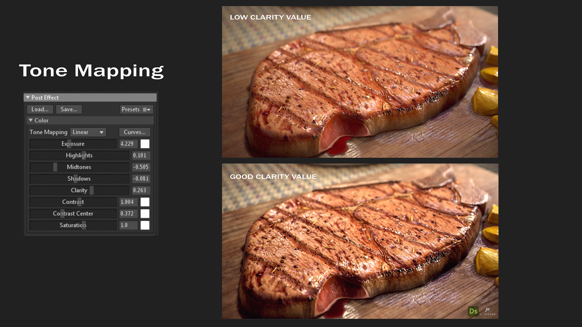
Tone Mapping Section
This part allows changing a few settings like exposure, midtones, contrast, and saturation.
A very useful parameter that helped me improve the render quality a lot is called Clarity: this increases the definition of fine details in the rendered scene.
- Sharpen: This section is commonly used to reduce blurriness by enhancing the crispness of details, making the image appear clearer and more defined.
- Bloom: This effect causes light to extend from the edges of bright areas, creating a soft, glowing bleed into darker regions. It is a subtle effect, often barely noticeable, but adds a delicate glow to the image.
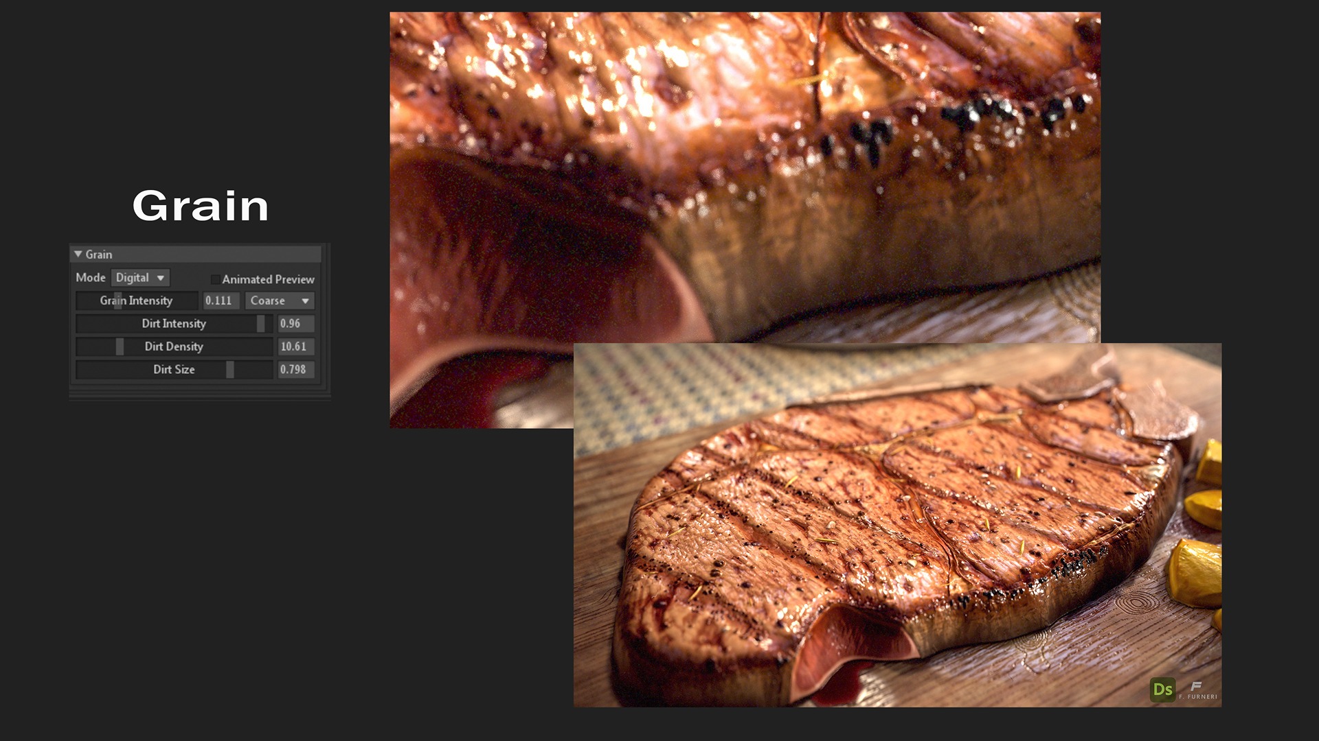
- Vignette: This section darkens the edges of the screen by applying a dark circular mask around the rendered image. The effect is also subtle, with the darkening mostly visible at the corners, helping to draw the viewer’s attention more towards the center of the image.

- Grain: To mimic the appearance of real cameras, adding a bit of grain can make a significant difference.Grain is most noticeable in the shadows, and in this case, I have introduced only a small amount to achieve a more authentic look and realism.In digital imaging, grain is primarily caused by the noise in the image sensor.
All of the previous effects, combined with the Ray tracing algorithm, help make your render stand out, ready to be showcased on major platforms and reels.
Conclusions
Thank you so much for following along with this interview. I hope it provided you with a clear understanding of the key steps involved in creating a procedural steak in Substance 3D Designer. I would also like to extend my gratitude to GamesArtist for the opportunity to share this breakdown.
If you have any questions, feel free to reach out to me on LinkedIn, and stay tuned for new projects on my ArtStation.
Read more articles
You might also like these articles.