Bubble Wrap

Introduction
Hello, my name is Ishan Verma. I am a Senior Material Artist with five years of experience in AAA game development.
In addition to being a self-taught artist, I am also an Unreal Engine and a Substance 3D Designer enthusiast.
Currently, I am working as a Senior Material Artist at Nodding Heads Games, the developers of Raji: An Ancient Epic video game.


Why Bubble Wrap?
What my perspective holds is whenever I want to learn something new, I do it in a creative and practical manner. In my opinion, procedural materials offer flexibility, modularity, and reuse. They also enable fast workflow iteration (the initial cost of creation remains, but updates can propagate across assets and variations can be created very quickly).
I used a small graph probably because I wanted to do this in a genuine production workflow. Moreover, I wanted to use ray traced transparency and refraction, which is why I used Bubble Wrap. As a result, I decided to create it in Substance 3D Designer and later showcase it using Unreal Engine 5.
Material’s Look
When I create textures, I constantly evaluate them on the fly. If my heights or normals need more work, then I won’t finish out the details but the balance scale, level of detail, texture quality,. I always export a rough first pass of the texture set to the engine for checking it . Surfaces are very similar to the way I approach them. I evaluate surface qualities individually, and then blend them to come up with richer responses.

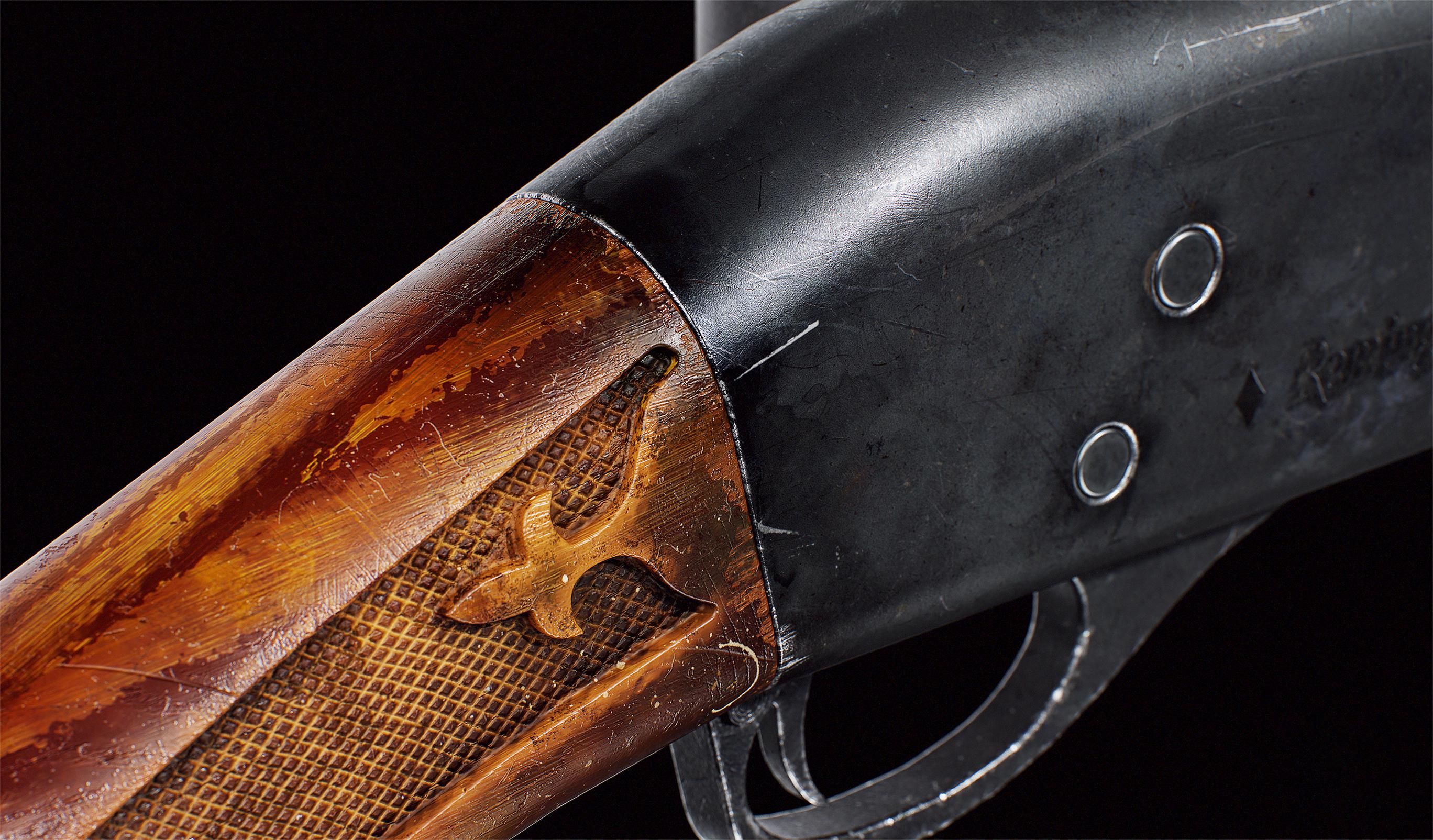
References:
Below are a few references that helped me understand the size, shape, forms, and characteristics of the wrap.

Height Building:
- Base Bubbles
To begin, I created the base bubbles using a tile generator node with a paraboloid shape, then tightened it using levels and blur nodes and blended it with the main tiling.It will now look like a softer version of an inverted honeycomb.

- Popped Bubbles
I started by making a crease shape, which is pattern specific at 0.05, scaled at 0.53, and randomly rotated. For that I used another tile generator, but here I used Waves shape input.
To add some realistic folds to the crease, I warped the tiling with Perlin noise at a scale of 64 and an intensity of 0.03.
In order to blend these creases on top of the bubble shape, I used a second tile sampler, but this time I added some random luminance, inverted it, and tightened up the shapes a bit. Overlayed a 16×16 White uniform color and blended the crease on top of the main tile generator using the mask I just created.

- Surface Deformities
My next step was to deal with surface deformities, which has to do with removing the visual procedural feel. To achieve this, I started with a Fractal sum base 1 node which was blurred out twice and leveled. Then the main tile generator is warped so bubbles can have that feel to it.

- Surface Fibre Noise
In this case, because the surface is still smooth, I layered on top of it a layer of fibrous noise. To make this noise, I produced some scratches by using a scratch node, transformed the result, and used multiple levels to layer it. I then multiplied by 1 on top of a BnW spot for more variation on the surface.

- Height Map
By multiplying the blurred out Fractal Sum base that we created in the Deformities section with bubble wrap tile setup, I added more volume and readability to the height.

In my next step, I blended some light blends with slightly levelled height data and blurred out the data thrice, altering its intensity, to add some variation, as well as warped the main height map with the blurred map to give more depth to the height.
- Normal Map
I plugged my height into a normal node with intensity of 8 in order to give it a good amount of surface visual when driven by shaders in the engine.

- Roughness Map
The roughness map was created by blurring up the height map, leveling it up to midtones and inverting it. Finally, using a heightmap with a histogram select, I created a selective mask and added it to the roughness map.

- Ambient Occlusion
In order to create an AO map, I drove the height map to the Ambient Occlusion node with depth of 0.01 intensity, quality of 16.

- Transparency
In the same way as roughness, I inverted the height map and then added levels to tighten up the shape. Then, I used several histogram select nodes to blend various masks to give the transparency a bit of a realistic feel.

- BaseColor
Initially, it was tricky since it was transparent. So I blended a leveled up BnW Noise 1 with the height map. Then I repeated the process, but this time blended with a Dirt 1 node. On top of this, I leveled up scratches and embossed it with Dirt 1.

Using Emboss and Gloss nodes, I have added directional fake gloss tint to the Base Color using inverted height as a blend mask and several levels and blends to fix the values.

Taking it to Unreal Engine:
- Exported textures in .tga format with the following naming convention:
T_Bubblewrap_H.tga – Height
T_Bubblewrap_D.tga – Diffuse
T_Bubblewrap_N.tga – Normal
T_Bubblewrap_ARM.tga – AO, Roughness, Metallic
T_Bubblewrap_TP.tga – Transparency
Project and Scene Setup
First of all I created a project with Ray Tracing enabled, as well in project settings enabled the DirectX12 and turned on Ray Tracing from the rendering panel. Then, using three point lights, create a soft lighting scene with the particular rendering object in center.

Post Process Volume
The following Material is controlled using Post Process Volumes, so I created one and firstly fixed the Exposure values, then set the GI to Lumen, Reflections and Translucency as Ray Tracing and enabled the Ambient Occlusion from the rendering features.

Shader Creation
For the shader, I started with creating a base material, named it M_Bubblewrap. Then inside the material editor first I changed blending mode to Translucent and Lighting mode to Surface Translucency Volume. As well few more parameter tweaks as per in the image below:

First of all I started with setting a basic tiling setup using a mulitply of tex coord and float 1. Then for giving the illusion of depth, here I used a bump offset node where I plugged the tiling in coordinate, height map into height input and created a float 1 parameter to control height offset. Here I kept the height default as 0.035.

Here for basecolor, I kept it simple. First I plugged the tiling in, then multiplied AO from the ARM texture R channel with the base color texture to give a fake AO feel to it.

Next, I hooked up the Roughness from ARM texture’s G channel directly, and used a Float 1 with a value of 0.3 for the Metalness.

I used a normal map texture and plugged it into a flatten normal node. Additionally, I plugged in a Float 1 parameter to control the intensity of the texture.
Now, for Transparency I started with transparency mask I created earlier and multiplied it with a float 1 with 1.4 as intensity, this will control the depth of opacity.

Now, the trickiest part which made the bubble wrap to look more realistic was creating proper refraction. In order to get that I started a transform vector node to transform our normal from Tangent Space to World Space. As well here I have created another Float 1 to control normal intensity.

Then I added a Fresnel node to an alpha input of a Lerp node and added two float 1 nodes with intensity of 1 and 3 to the A and B inputs of a linear Lerp node.
Once done, I plugged all of them into their respective inputs. A graph shot is mentioned below for better understanding:

Camera Setup and Render Shots
In order to have some good portfolio renders, I started with adding a CineCameraActor to the scene with Lens setting as Universal Zoom, Aperture as 1.2 and with focal length of 32mm.

Then in the post process settings, I added bloom with 1.2 Intensity and some vignette with value 0.35.

Taking Renders
You can take high-quality screenshots with Unreal Engine by selecting High-Resolution Screenshot from the viewport drop-down menu. A pop-up will appear. From there we can set up a size multiplier by 1 to 4, or we can go with maximum numbers depending on the system.
Conclusion
I brainstormed a lot throughout the process from material creation to practical application. The outcome was worthwhile. I wanted to expand my skills in terms of developing a fully parametric material in a productive way. so I decided to give in a taste of unreal 5 to the process. Keeping on track is essential, as is learning things thoroughly as well as welcoming all your mistakes as serendipitous, as you never know if you’ll get an unexpected workflow from silly mistakes in Substance Designer. It’s important to experiment with different workflows until it’s worth continuing. Be observant and build a good visual library. This will really improve your detailed workflow.
Believe it and keep greatness coming!
Feel free to contact me on my :
ArtStation (https://www.artstation.com/ishanverma/)
Instagram (https://www.instagram.com/the_deteriorating_machine_/)
LinkedIn (https://www.linkedin.com/in/detemach/)
Thank You GamesArtist.
Read more articles
You might also like these articles.