Emerald Tiles

Introduction
Hi, I'm Max Eno, a Material Artist with a background in Architecture. I fell in love with material art and want to keep growing in this field.
I'm fairly new to material art and learning to create different surfaces in Substance Designer on my way to becoming a professional Material Artist.
Project & References
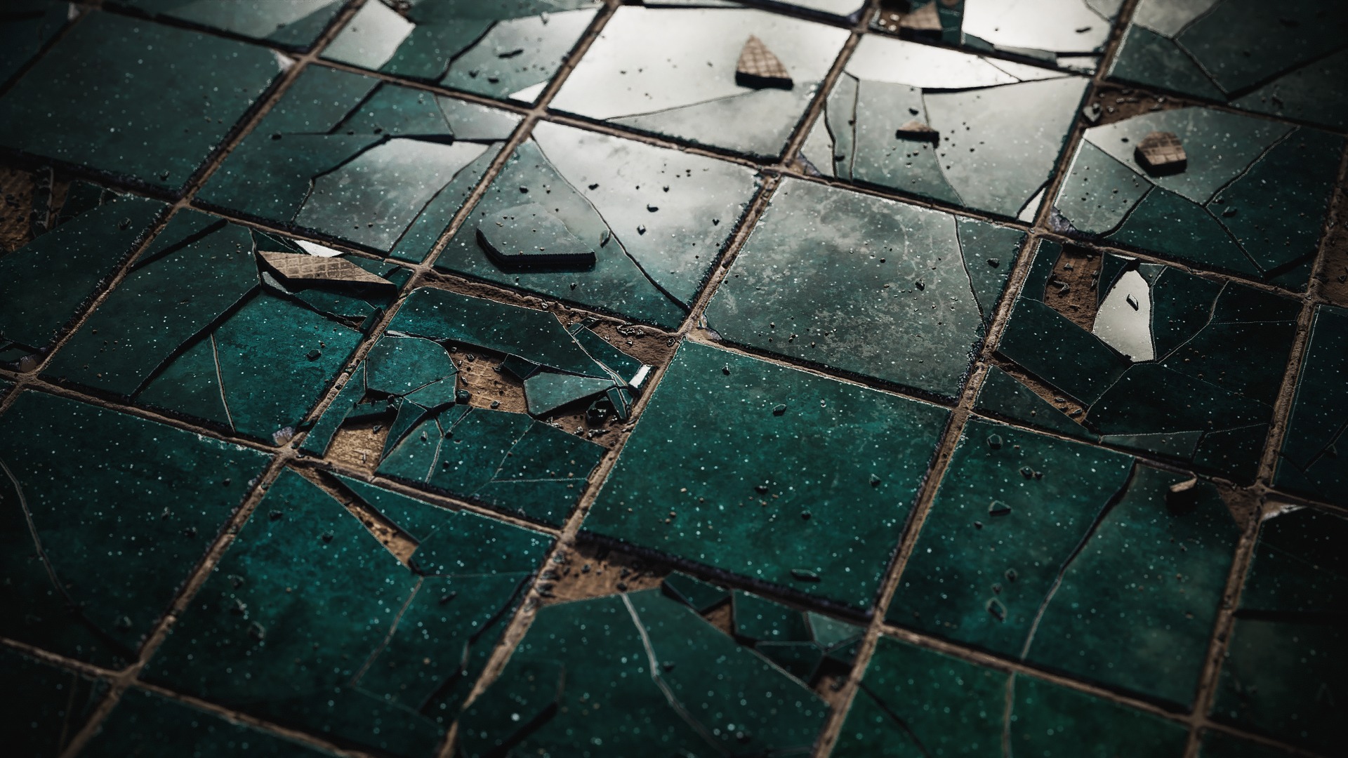
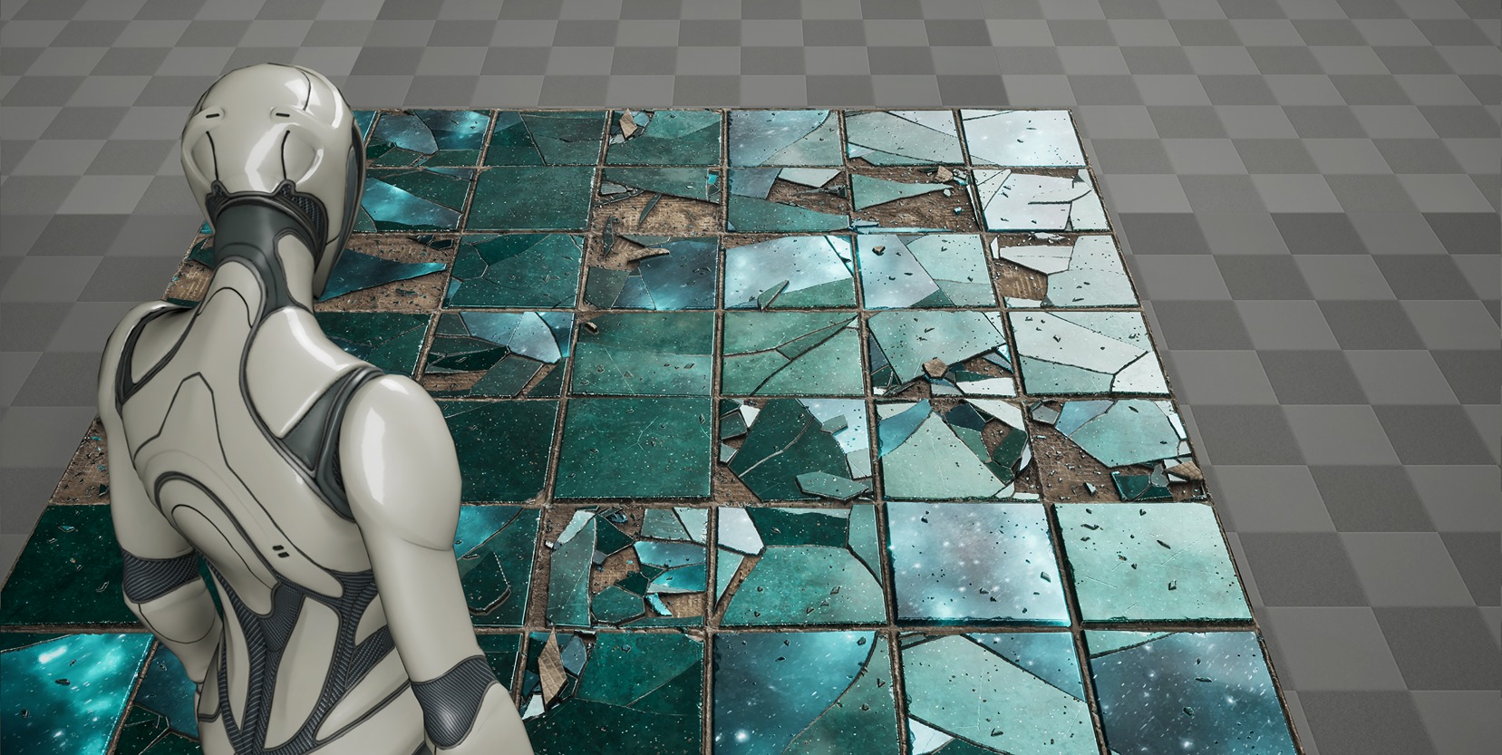
Every project starts with an idea. For this one, I aimed for space-green tiles that I could later make feel alive in Unreal Engine.
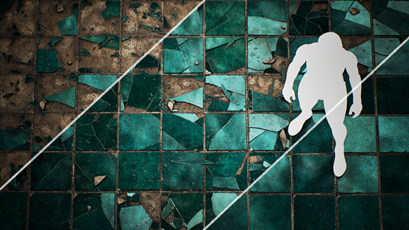
I always make a short comic for every artwork I work on, my lil creative ritual.
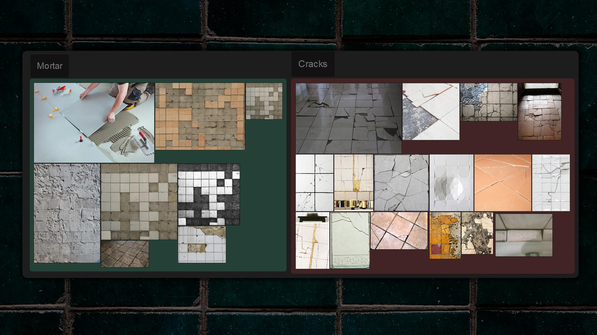
Since the material is procedural, I studied how mortar is laid, how tiles crack, and how fragments distribute across a surface. The goal was to reproduce believable patterns without turning the node graph into a tangled mess.
I really enjoy creating procedural materials because it’s a fun challenge.
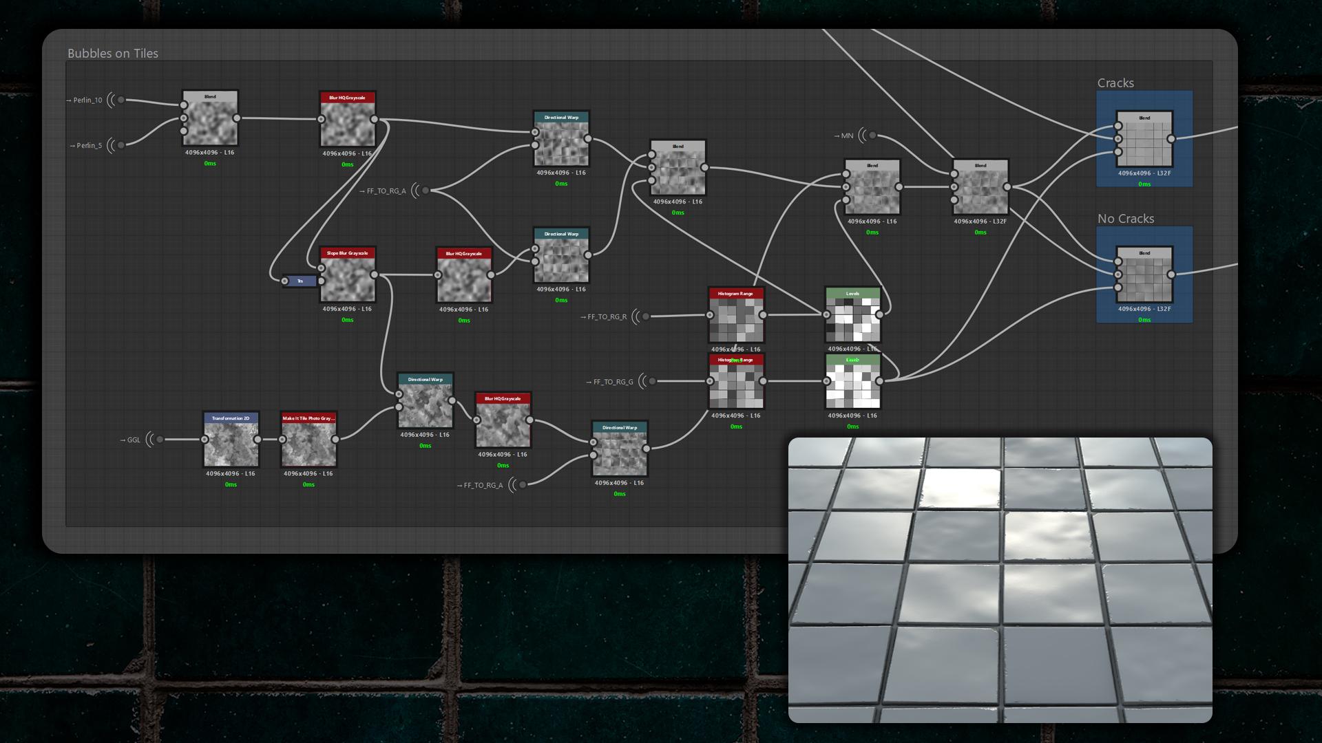
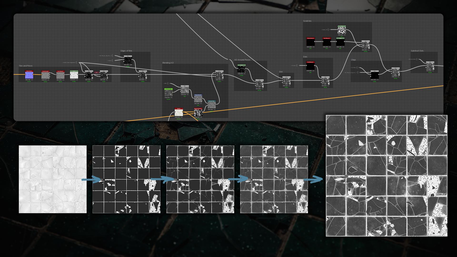
There are always many masking and switching involved, so don’t worry if your graph gets messy – keep it organised and give your dot nodes (portals) non-confusing names. In the end you can end up with something like this:
Creating Tiles
I started with a simple Tile Generator, warped it with the Perlin, and ran a Flood Fill (FF) immediately after. That helped later with Slope Blurring and also warping noises.
A lil tip: split the FF to RC into RGBA channels to get four greyscale masks. I also stack my noises at the beginning of the graph so I can reuse them later.
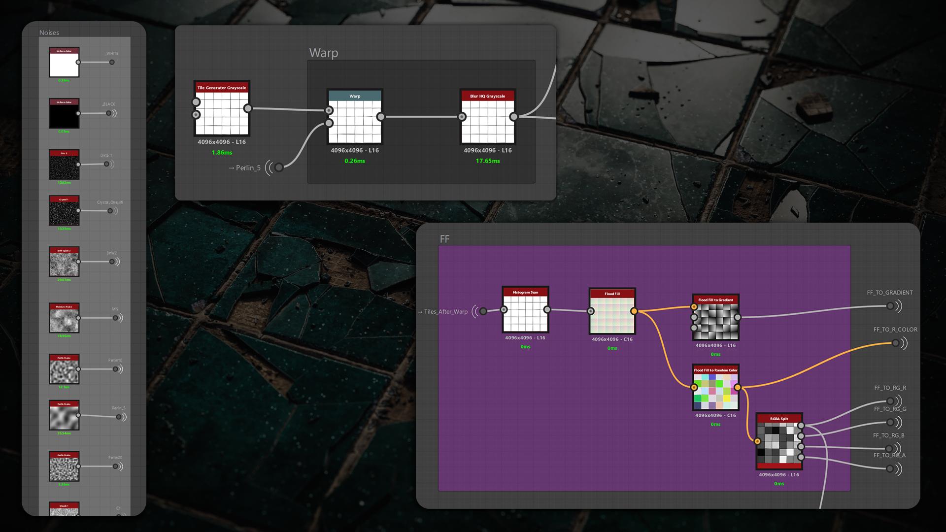
I used Directional Warp with one of the FF RG channels to warp my noises and create a mask for the first Slope Blur.
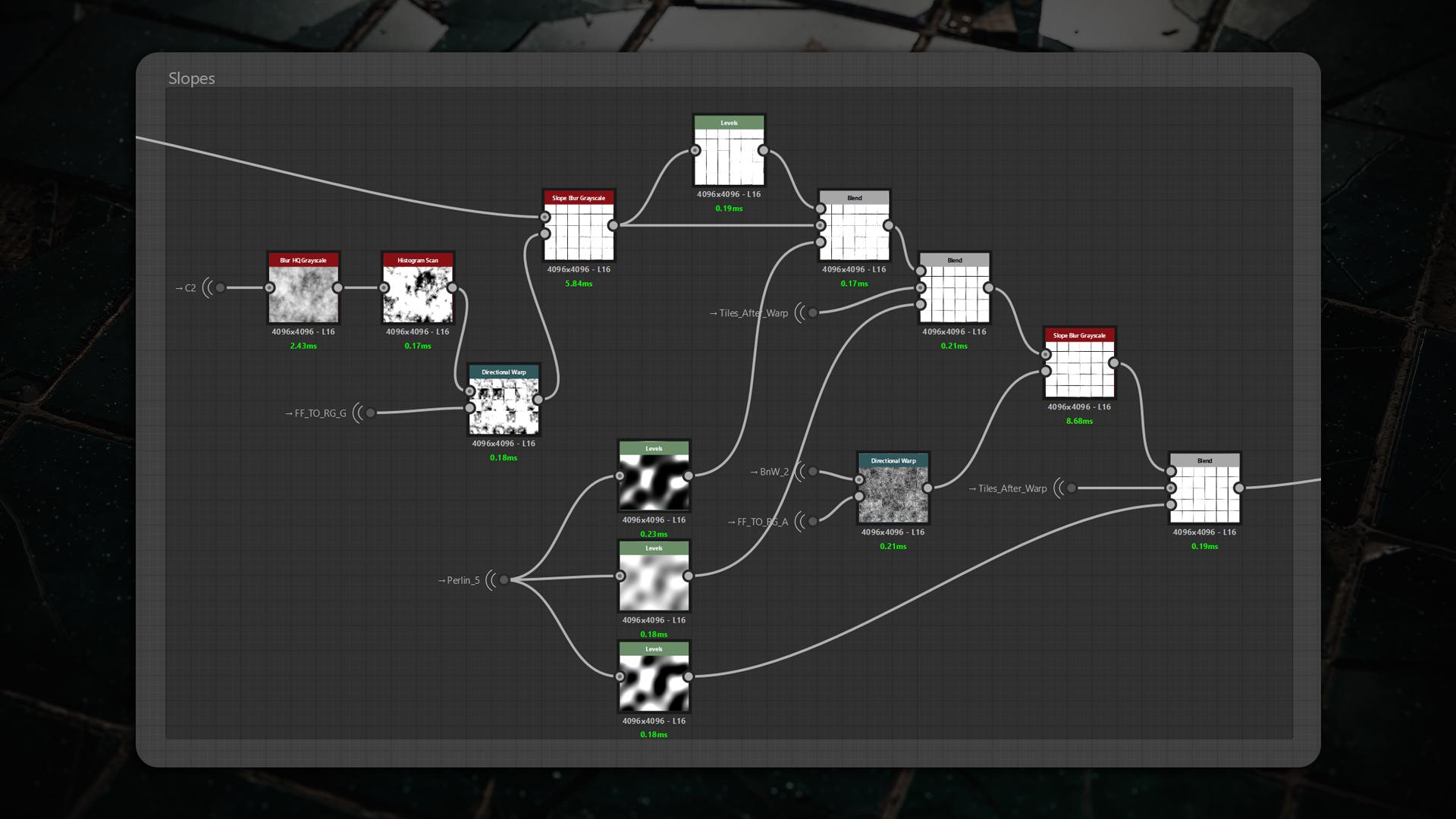
I repeated the same technique for the second Slope Blur using a different noise. I relied heavily on Perlin masks so the damage distribution would look more random.
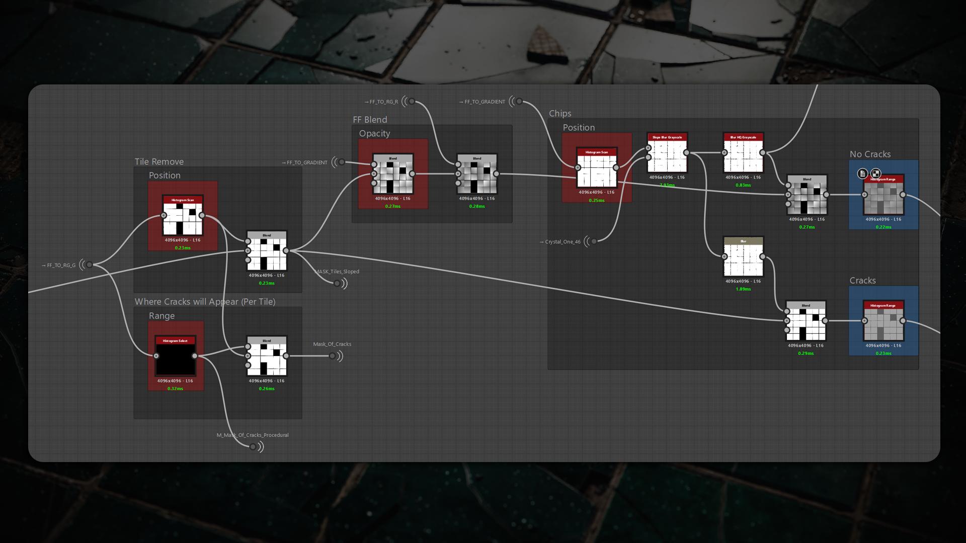
Before blending my FFs, I created a mask to remove tiles and mark where cracks would appear, then added visible chipping along the edges.
Importantly, when blending my FFs I made two versions of the tiles – “with Cracks” and “without Cracks” – because cracked tiles get their own custom FFs for each broken piece.
Next, I added bubbles on the tiles using Galvanic Grunge, applied Slope Blur, and used Directional Warp with my FF masks to distribute them across the tiles with varying strength.
Crack Generation
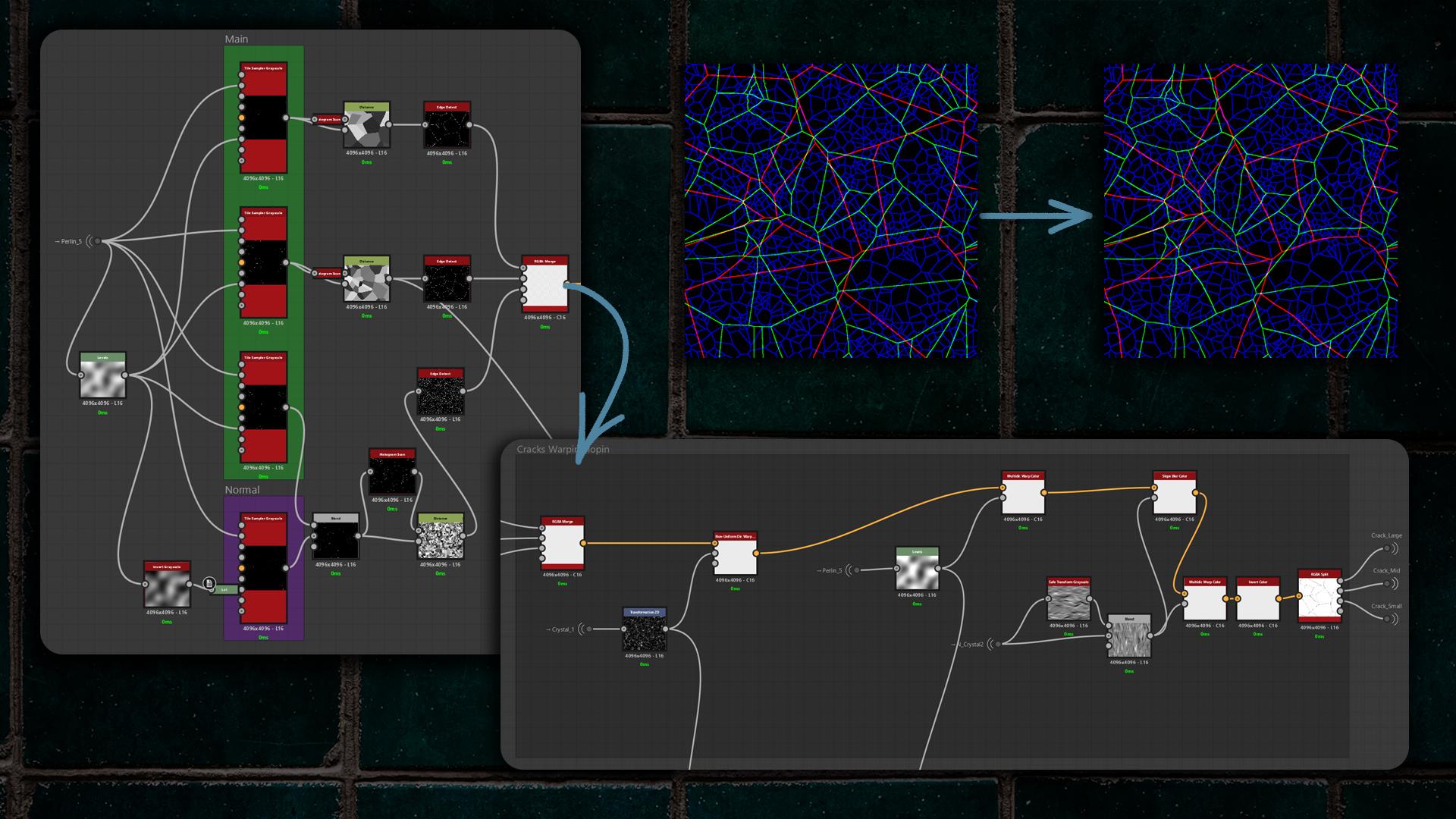
I used four Tile Samplers, scanned them, and combined their outputs with a Distance node – the standard approach for creating cracks.
After edge-detecting each result, I packed them into an RGBA Merge so I could warp and slope them all at once instead of processing each channel individually, which improves performance. I then unpacked them with RGBA Split.
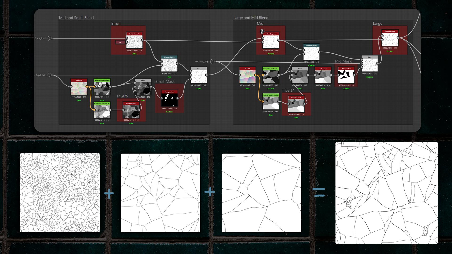
This produced four crack levels – Large, Mid, Small, and Normal cracks that I can toggle and blend.
When it came time to blend everything, I recalled Johnny Nodes’ excellent tutorials on tiles and cracks.
He shows how to blend crack layers by using FFs, Directional Warping, and masking each crack level to achieve correct, non-destructive blending.
Here I used the custom node called Better Flood Fill, so you don’t have to create a Distance node and run a histogram scan to fill the gaps between tiles and produce a perfect mask for blending.
(I’ll leave the links to every custom node at the end of the article.)
Next, I made additional adjustments to the cracks, tweaking their thickness and slope. In addition to FF, I created an impact-control mask so the broken pieces would look more realistic. Then I Vector Warped the cracks using my FF to Random Color so the cracks would distribute randomly across the tiles.
Removing pieces was simple. I took the FF, converted it to random greyscale, and picked pieces with Histogram Select.
The important part is the Vector Warp – its parameters must match the Vector Warp mentioned above.

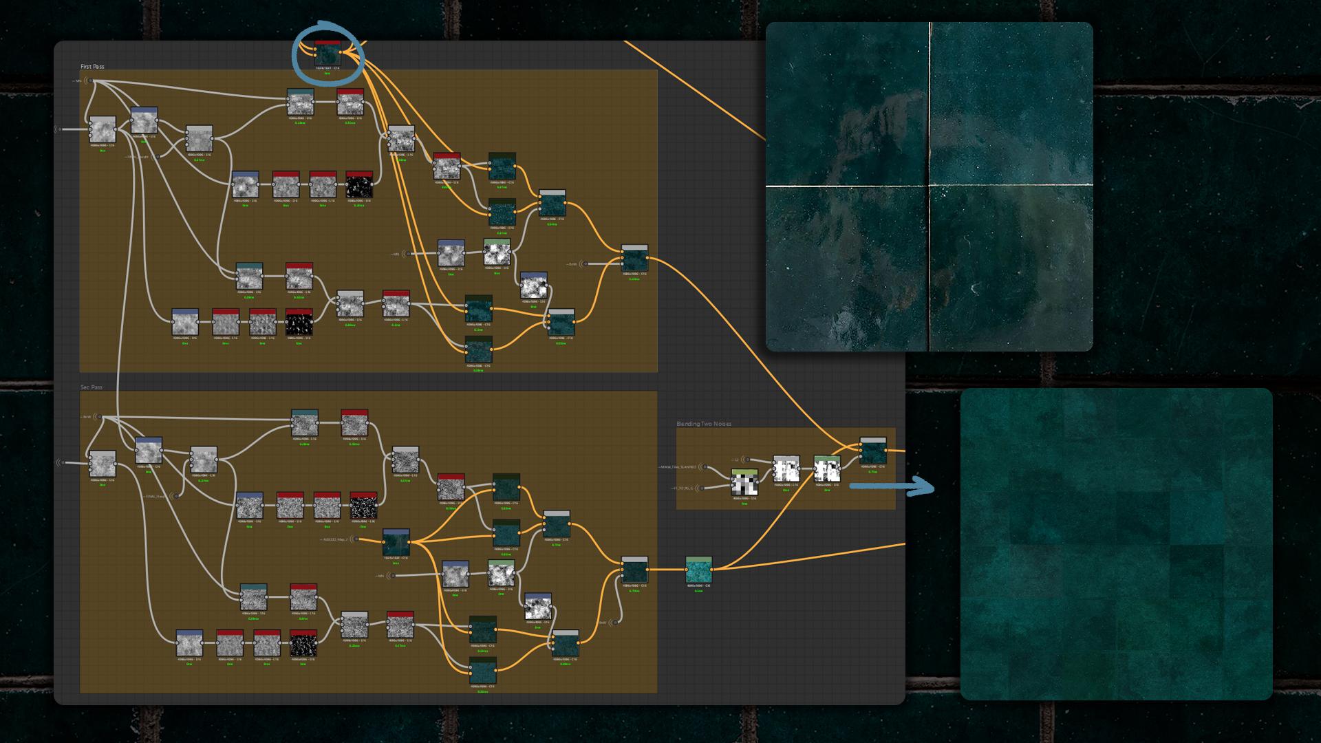
Mortar
A year ago I was practising tile workflows, and Csabi Kalanyos showed a great example of making mortar in his tutorials.
For the mortar I used two blended layers: the first is a Square Pattern made with a Tile Generator and warped it, the second is basically warped grout lines – I started from a Linear Gradient, warped it with Vector Morph, and used Perlin noise for masking.
I copied both masks on top of each other, added a bit of noise blending, adjusted the result with Histogram Range, and that produced the final mortar.
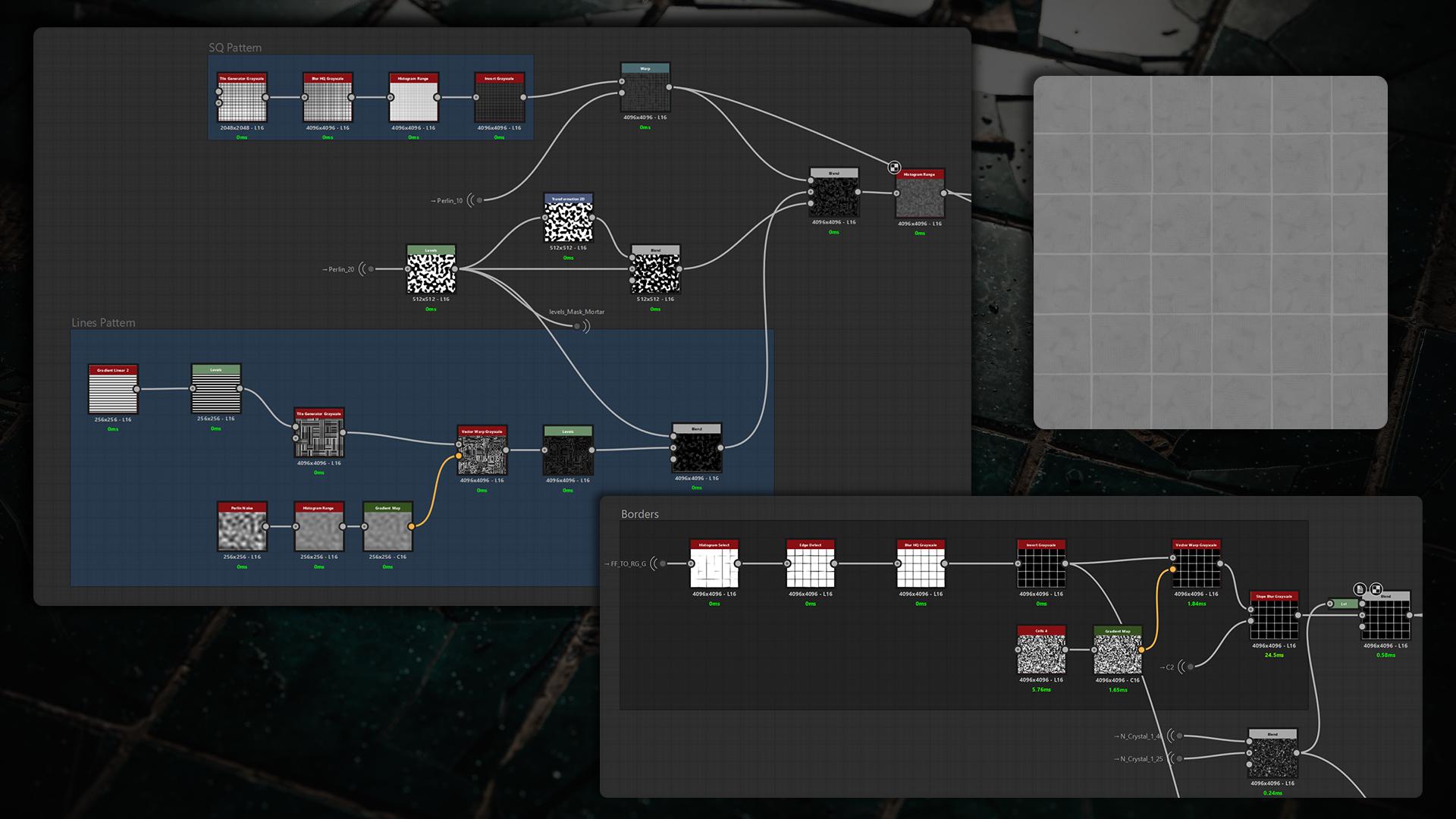
I used my scanned tiles and ran Edge Detect to control the border thickness, then inverted the result. I warped and applied Slope Blur to the mask, and added a parameter that removes borders by subtracting Crystal Noise.
This setup lets me precisely tune border width and selectively erase mortar edges for a more natural look.
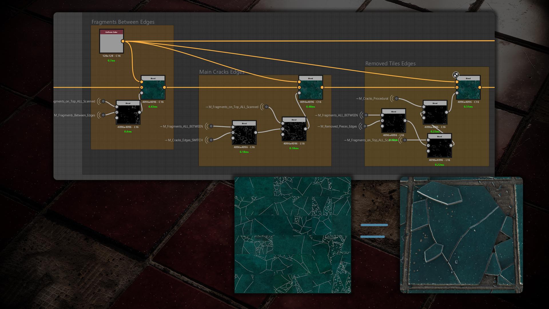
Fragments on Tiles
To create fragments, I used the existing Mid crack layer: I converted it with Flood Fill to Random Color, unpacked the channels with RGBA Split, then used Histogram Select to pick individual pieces.
I scattered those pieces with Shape Splatter and exposed a Mask Random parameter to control the amount and distribution of fragments.
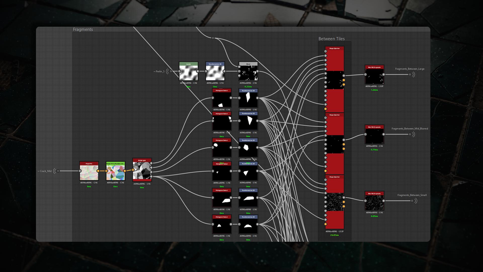
Same process for fragments on top and flipped tiles: I created a mask so they appear only on tiles and only rarely on the mortar.
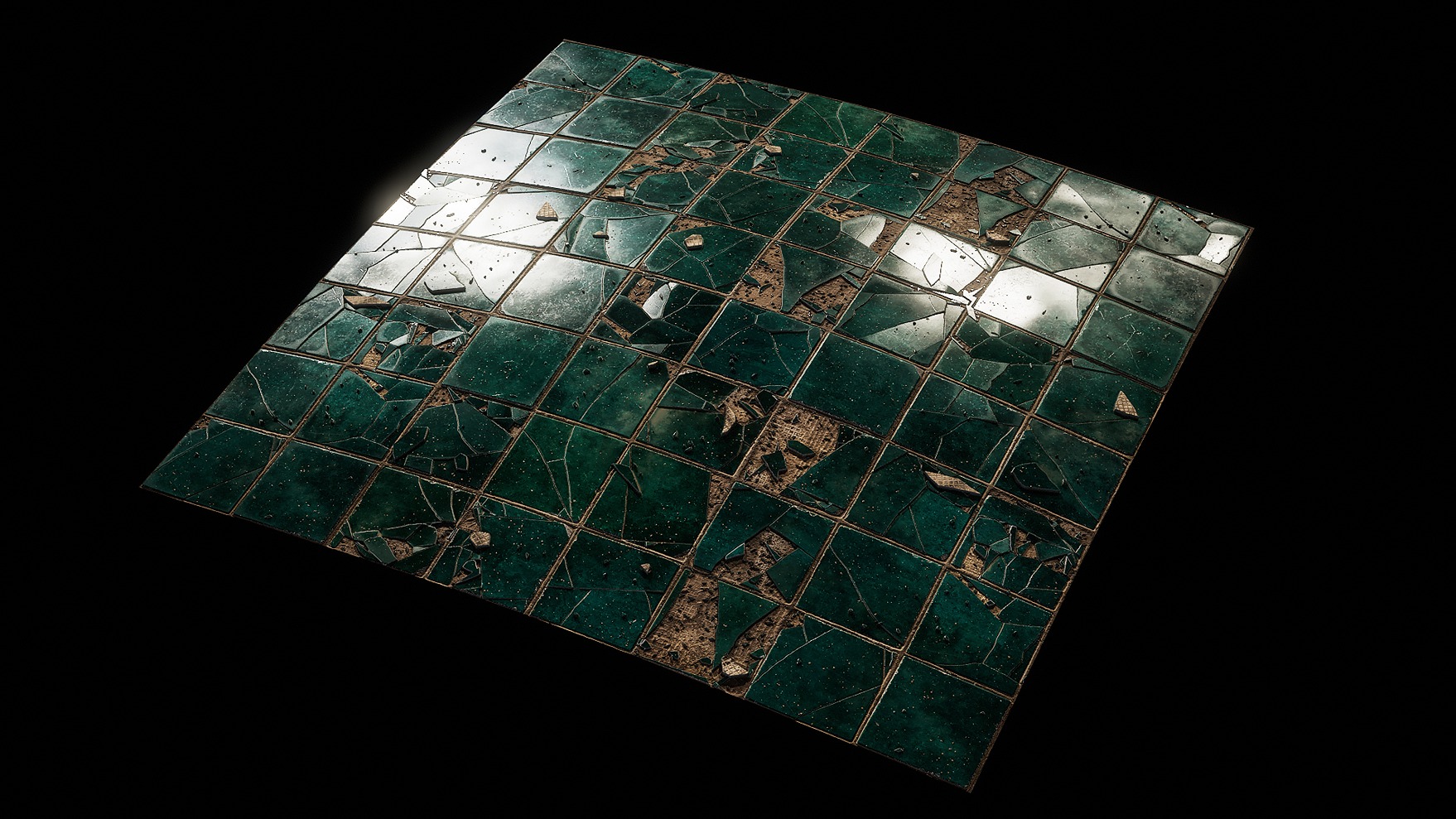
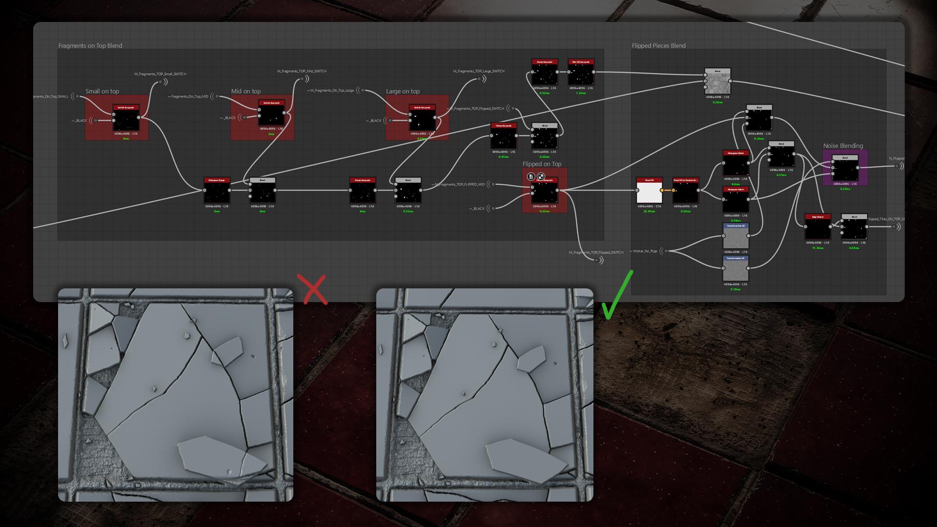
Blending it all Together
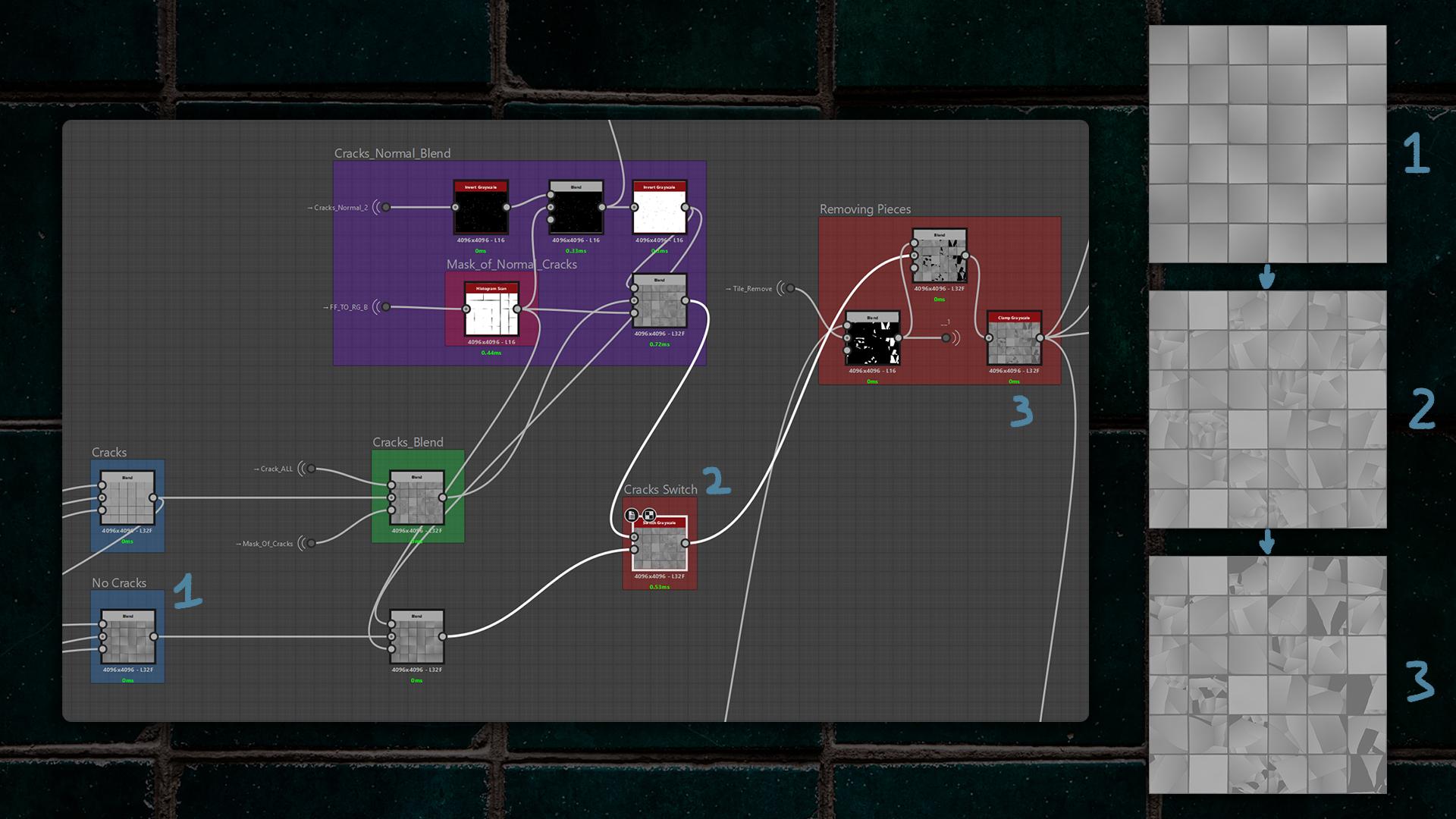
As you may remember, I split the tiles into two switchable versions – without cracks and with cracks – so the FF works correctly for both.
I blended the minor (normal, I just call them that because they’re tiny) cracks over both versions, then added the main cracks themselves, using a mask to control where cracks appear.
I also implemented a Pieces Removing option: with the prepared mask, I can remove selected tile pieces.
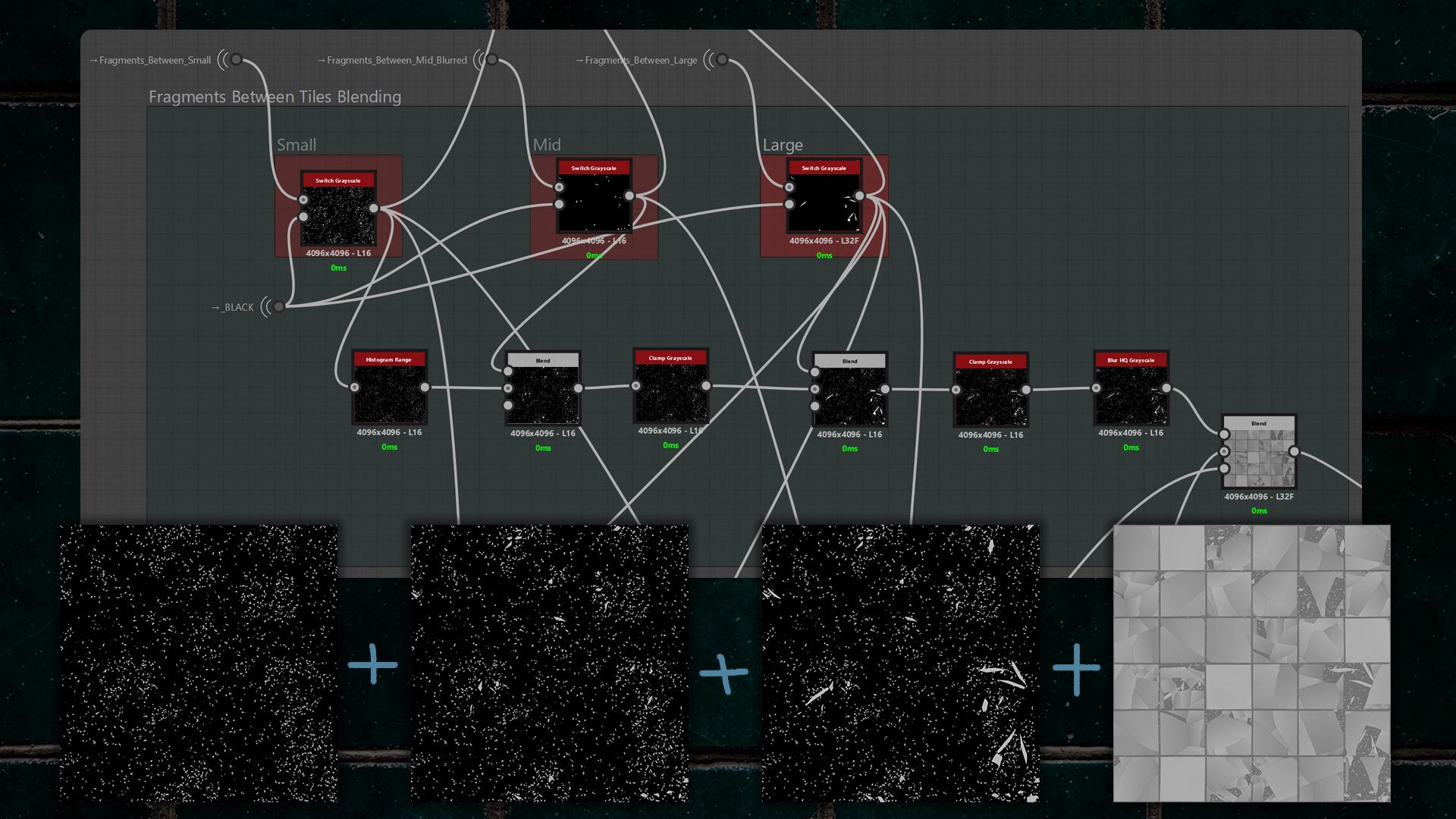
Before blending the mortar, I blended the “Fragments Between” and added switches to toggle them on or off.
It was important to make the fragments overlap correctly, so I used clamps to prevent pieces from intersecting each other incorrectly.
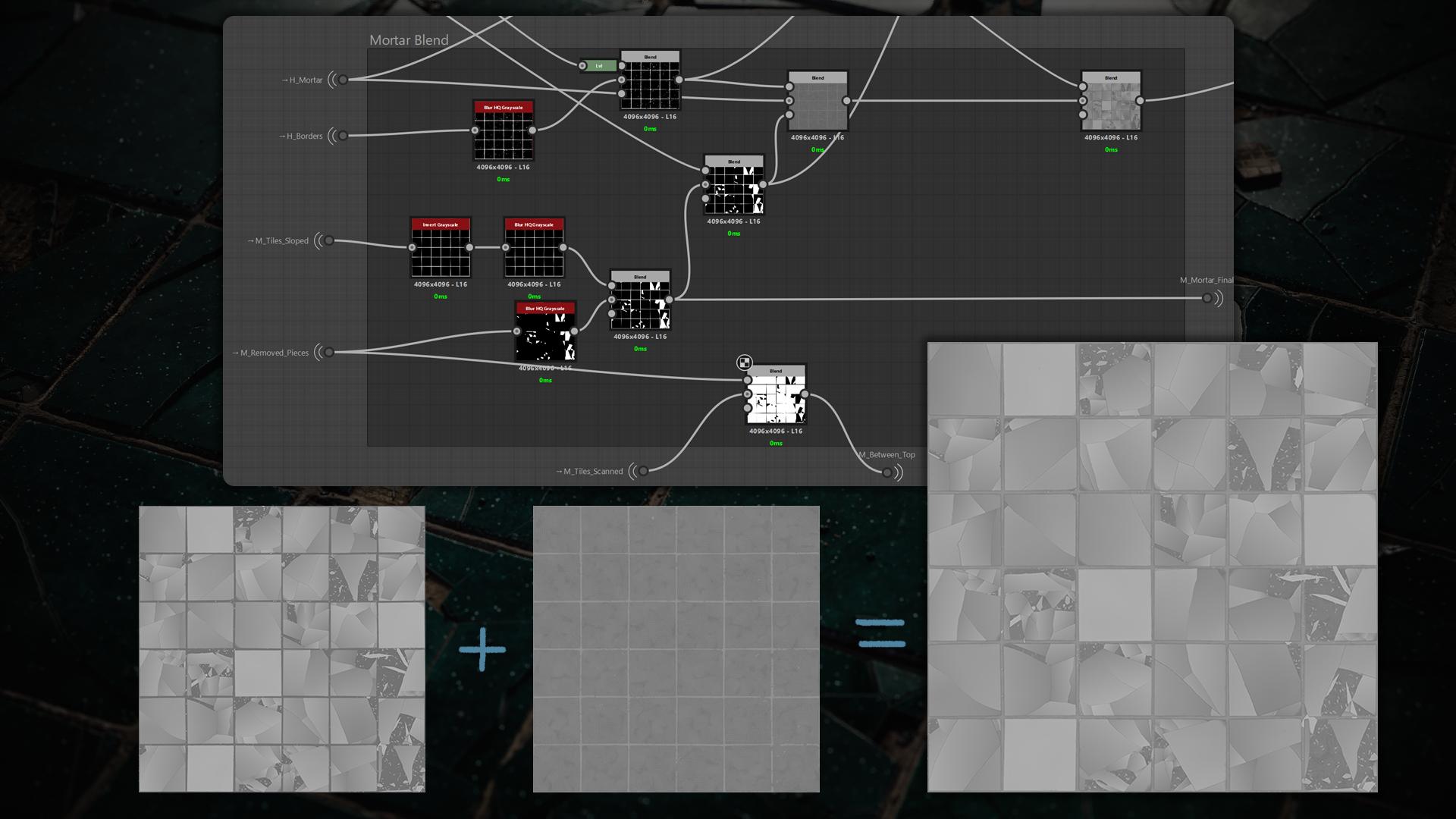
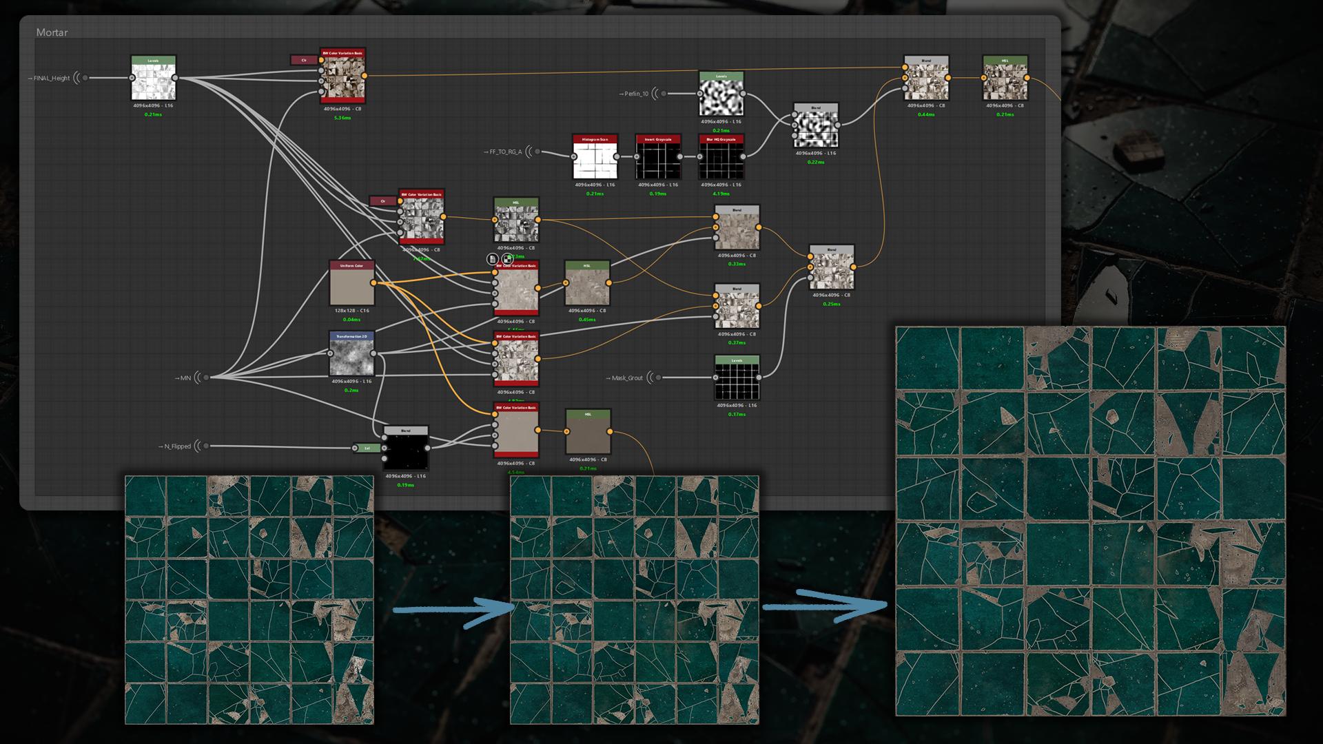
It was time to blend the mortar with the mortar borders. First, I blended the borders with the mortar pattern, and only after that did I blend in the tiles and fragments themselves.
I used the mask of all fragments to subtract some of them from the borders so the fragments would sink slightly into the mortar edges.
Top and flipped fragments were blended like the Fragments Between, given varied heights, and clamped to avoid improper intersections so they align correctly with the cracks.
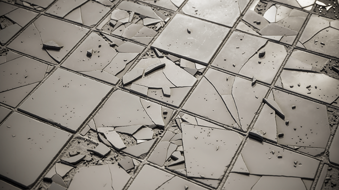
In addition, you can add small pebbles, leaves, or soil to taste. This is what we have so far with the Height:
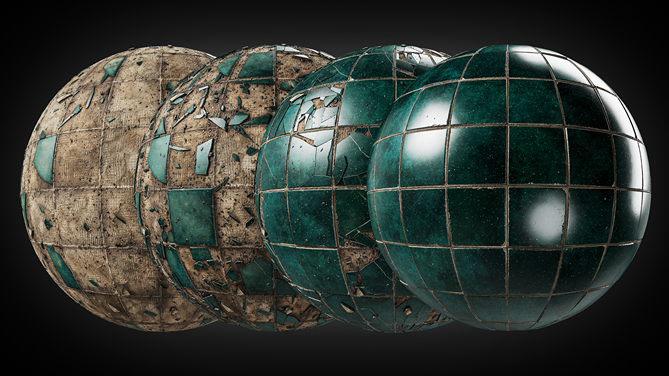
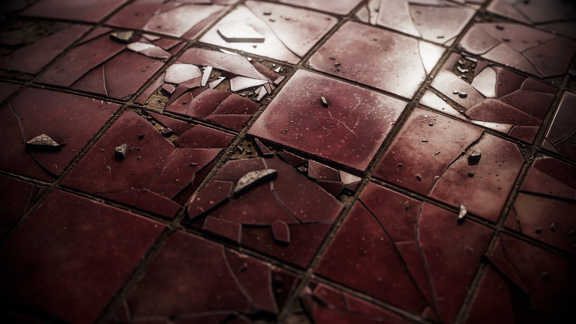
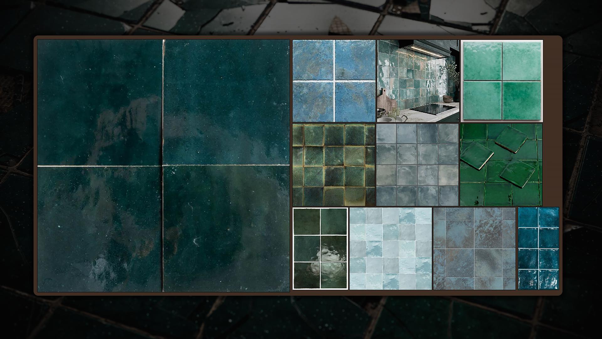
Color
When it comes to color, it’s always the hardest part of the material for me. You can have a great height map that looks convincing in clay mode, but if the color isn’t right, the whole material can fall apart.
I study how professionals approach color – Johnny Nodes showed a useful trick: run your color reference through Gradient Dynamic with mixed noises.
I did two passes and blended them: one brighter variation and one darker. I combined them using a Flood Fill mask and multiplied noise to add subtle variation.
To get clean edges for all broken pieces and tiles, I ran Edge Detect and used multiple subtract blends to create precise masks.
For the mortar I used Ben Willson’s BW Color Variation Basic node. It generates controlled hue and value variation from input masks and procedural noise.
I layered several instances of the node, mixing different colors and masks to achieve subtle, mortar-specific variation.
Roughness
There’s nothing particularly special about my roughness.
I started building it from Curvature Smooth, then added AO, noises, and other small graph elements to achieve a decent roughness map.
Unreal Engine
Just in case other beginners want to create an Unreal material but are struggling a bit, I hope the way I built it will help.
Here I began with a Distortion, created the UVs and a Panner, and did the same for my Volumetric texture.
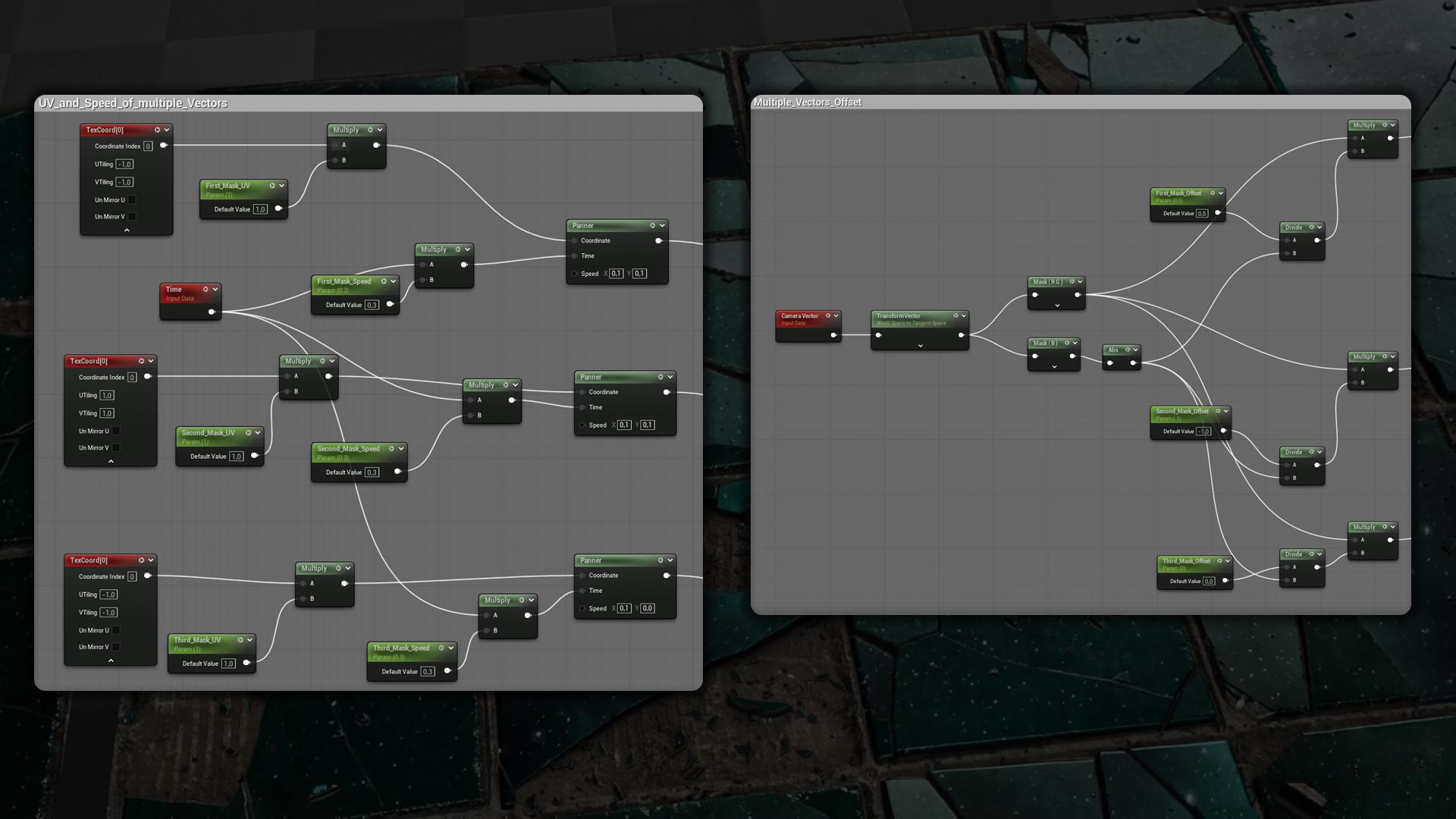
Next I created a Camera Vector for the illusion, but that only works for a single moving vector – what if you need multiple vectors?
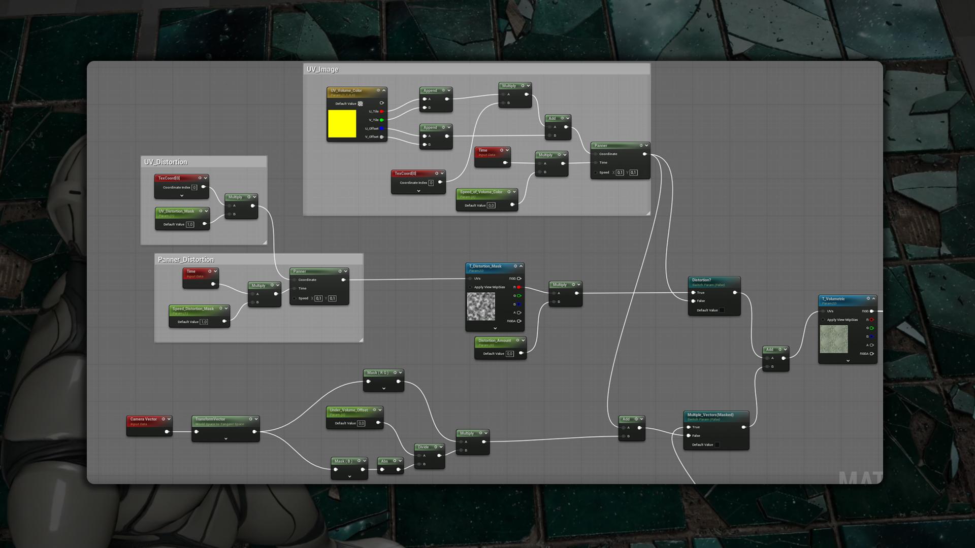
I created three different TexCoords, flipped one so its UV gradient ran the opposite way (you can set the UVs as you like in any direction), and added a Panner to each to control speed.
I also generated a Camera Vector for every TexCoord to control offsets individually.
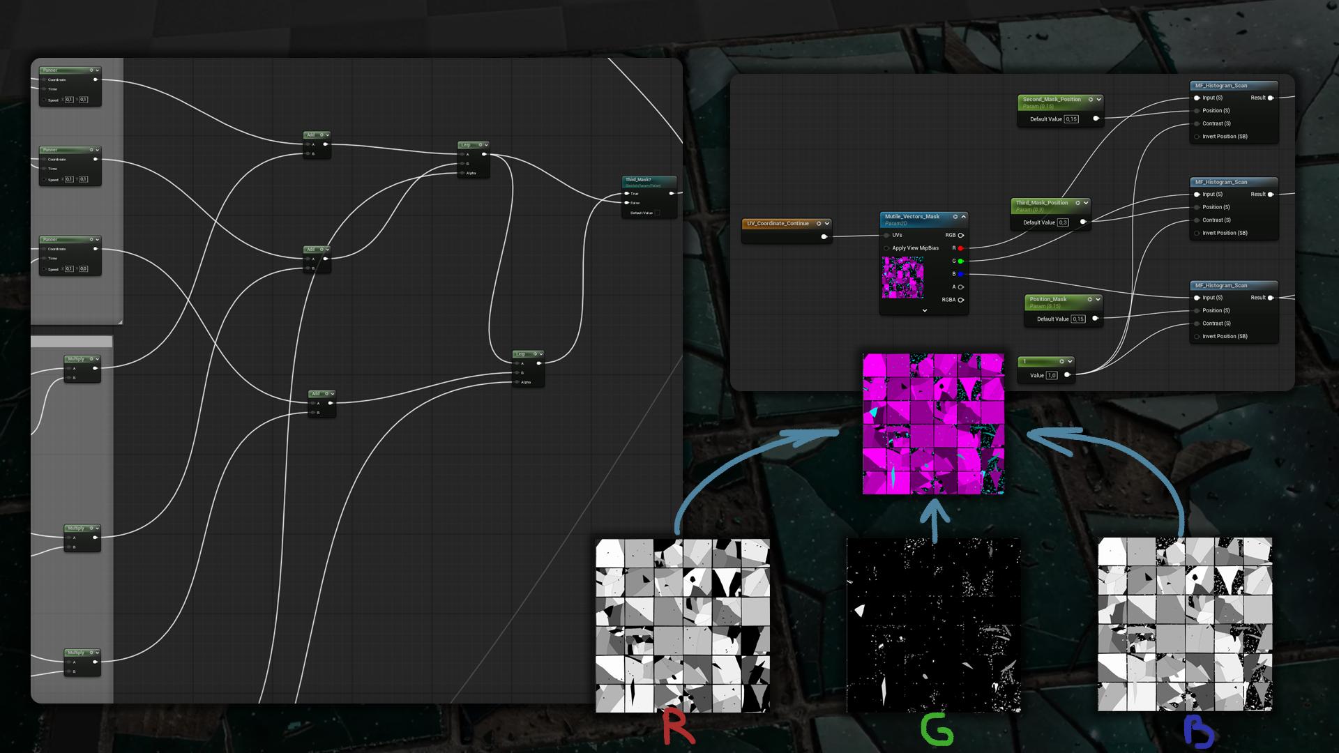
I added them and lerped them with a mask I created in SD. Each channel can be adjusted with this Material Function, similar to Histogram Scan in SD, to overlap the other masks.
The last channel is responsible for where the whole volumetric texture will appear.
Here is what we get after setting up all the parameters:
Conclusion
Thanks to Games Artist for the opportunity to share my experience through this article. I hope you picked up something from it, whether you’re a beginner or not. If you learned even a small tip, I’m happy.
Special Thanks:
Johnny Nodes – Johnny Nodes – YouTube
Csabi Kalanyos – ArtStation – Csabi Kalanyos
Resources:
ArtStation – Better Flood Fill to | FREE | Resources
ArtStation – BW Color Variation – Substance Designer Node | Resources
Histogram Scan posted by JohnLogostini | blueprintUE | PasteBin For Unreal Engine
Read more articles
You might also like these articles.


