Introduction
Greetings everyone. I am Tran Vu Quoc Tri; my ArtStation profile is Dzoi Tran. Dzoi is my nickname.
I 'm a Material Artist, working at Glassegg – a Virtuos Studio in Vietnam.
Glassegg is a dynamic and creative environment; therefore, I have the opportunity to learn and develop myself every day. This job allows me to unleash my passion for art.
Goals & Inspiration
I want to introduce everyone to how I create a palm tree trunk material from Substance Designer without using scanned resources or bitmaps.
This enables me full optimization to modify the material later on, while at the same time practicing material creation using Substance Designer.
It was a great experience to collaborate with www.textures.com to create this material.
References
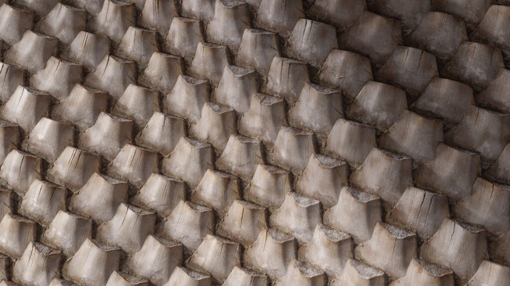
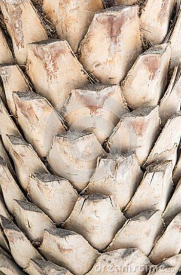
I stumbled upon a picture of a palm tree trunk material with a pretty nice shape on the internet.
Fortunately, it was created from scanned data, and I was able to use the scanned data as the main reference.
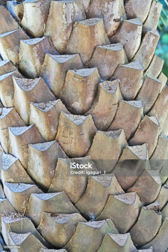
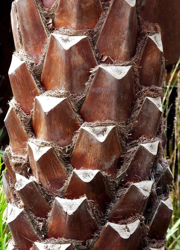
Combining with a few other pictures, I have a more general view of the shape of the palm tree trunk.
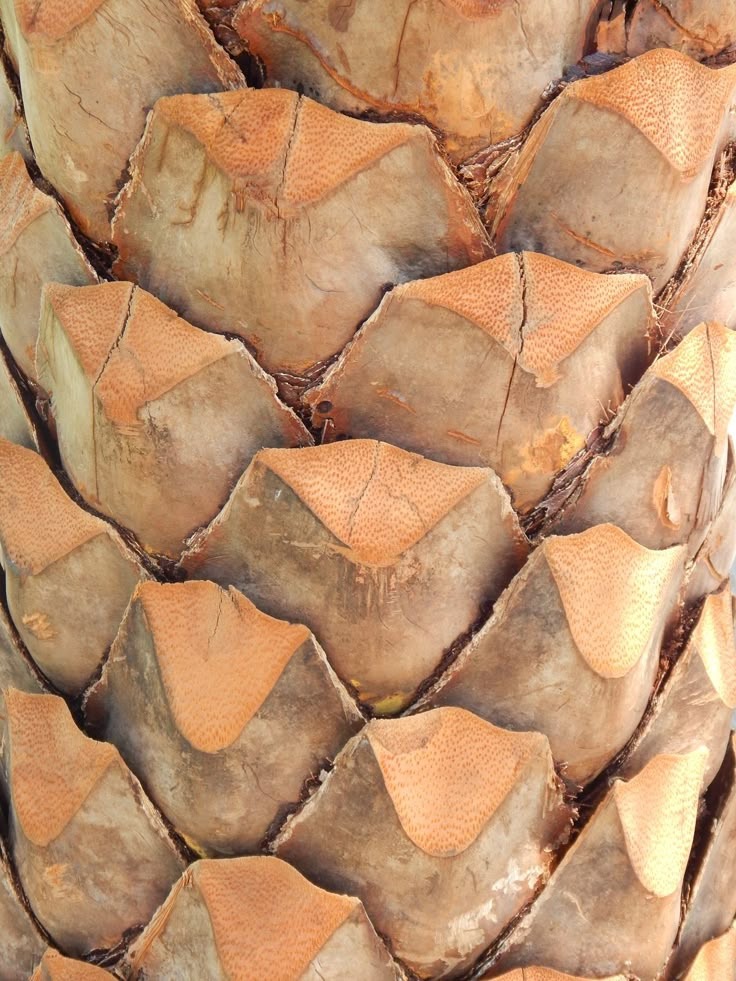
Analyzing References
At first glance, the shapes of the palm trees seem to be staggered and a bit random, but that’s my first shortcoming.
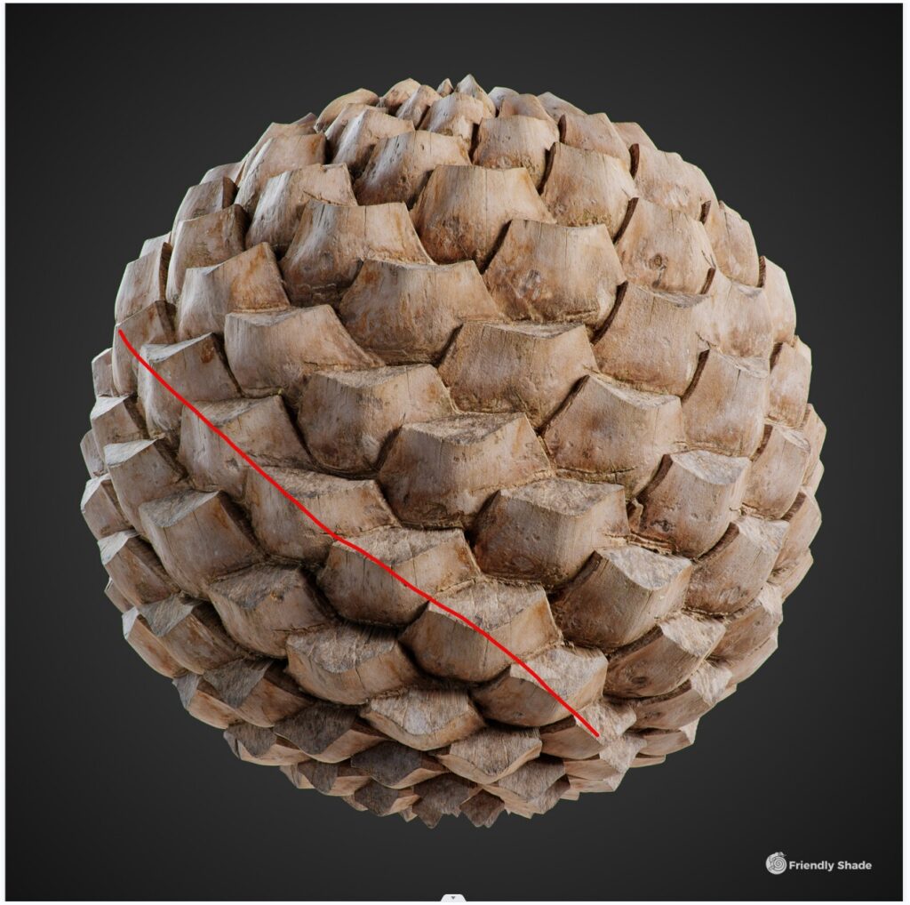
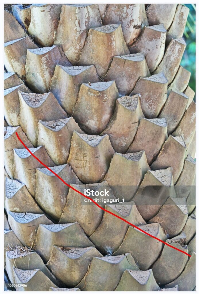
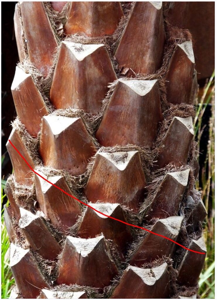
You can see that I marked the red line on each image.
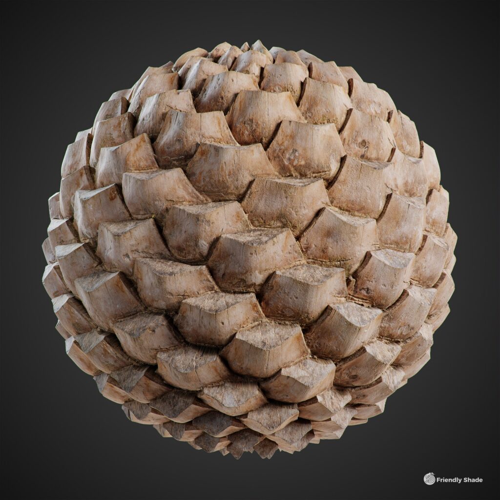
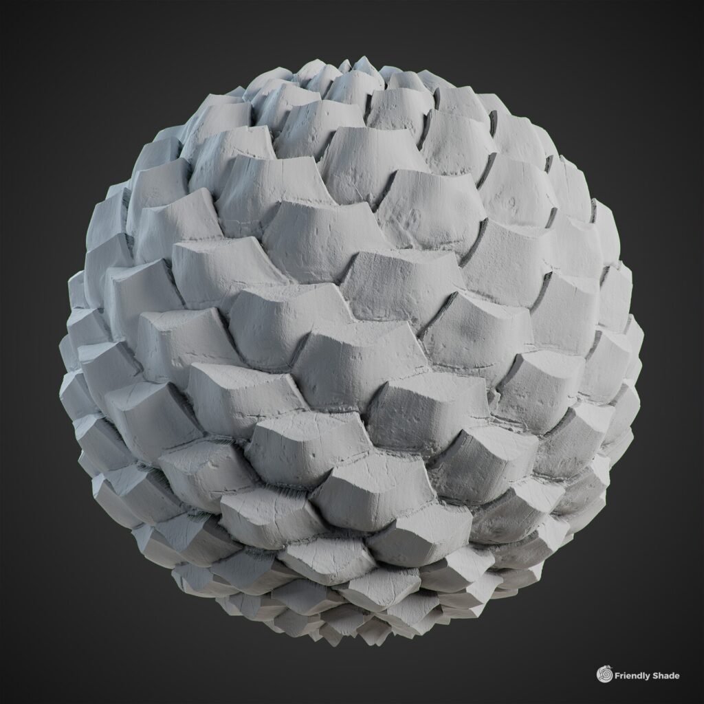
Comparing the two additional reference images that I found and the main reference image, we can see more clearly that the order of the shapes is formed diagonally compared to the main reference image on the sphere.
The shapes of the “scale” may differ slightly between the types of palm trees or due to the person who takes care of the palm trees, cutting the shapes long or short will create some slightly different shapes, but the rules of the shapes are the same among the same type of palm tree.
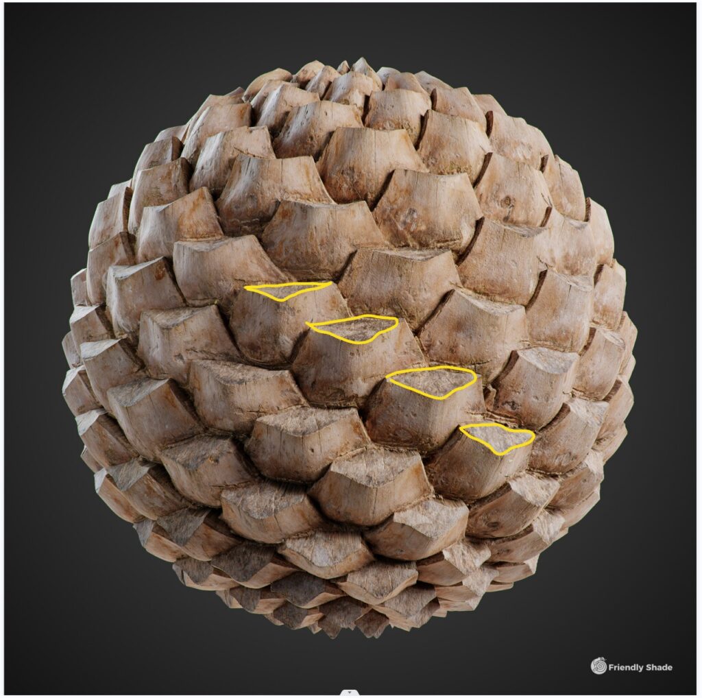
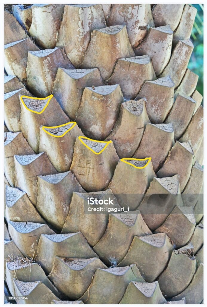
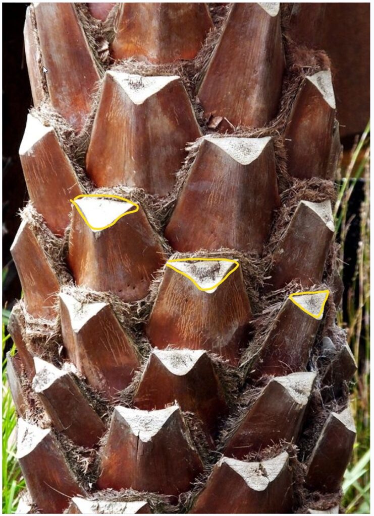
The part which is marked by the yellow triangle is the differences in the scale shapes from different types of palm trees.
In my opinion, the palm tree trunk material is one of the materials with a relatively difficult shape to handle.
Starting with the Height Map
When using Substance Designer to create the initial shape, I start from the part marked with the yellow triangle, “the scale.”
The Shape node, combined with the Shape Extrude node, can give me the desired shape.
This Shape Extrude node result is almost the same as if I used another software to model and then bake the height map.
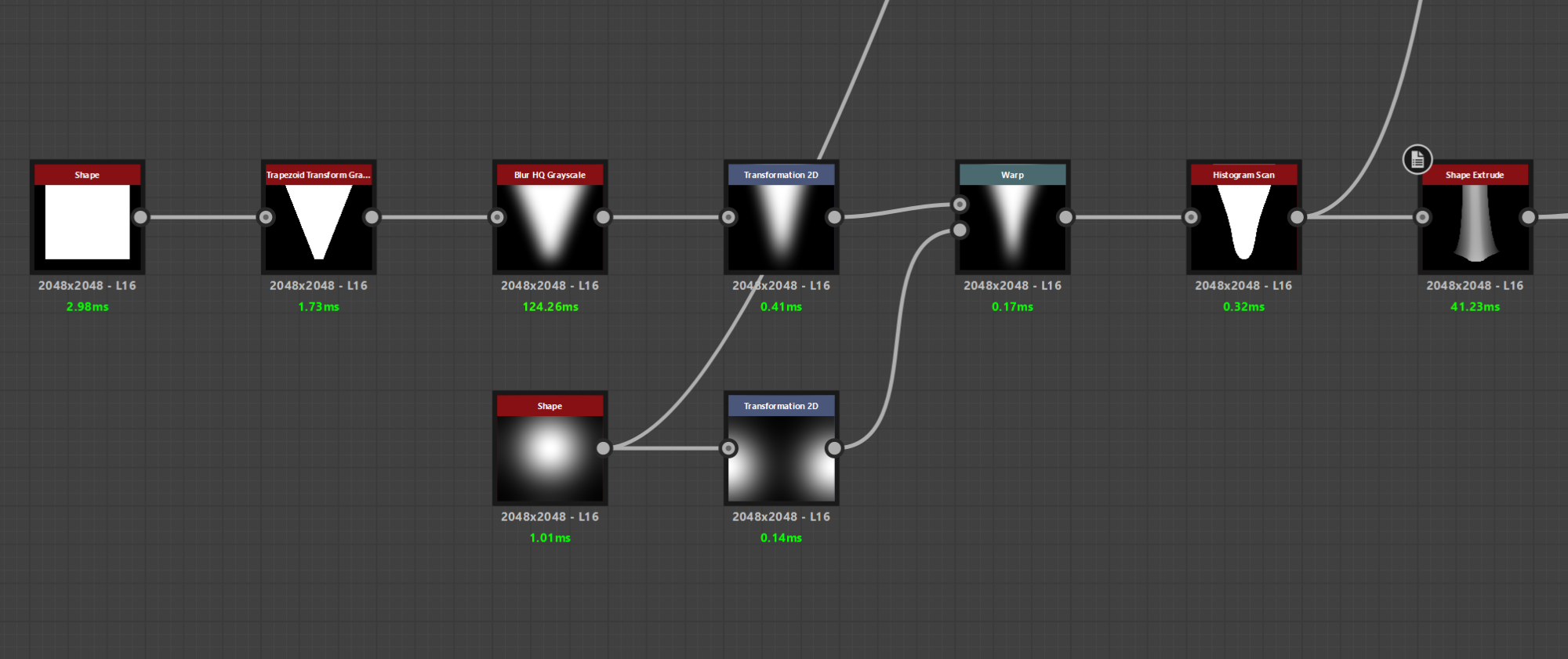
With this method, I have the necessary parameters to create many different shapes.
Also, it will be very beneficial for me in the process of adding diversity and natural looks to the materials.
However, I don’t start with a Shape Triangle node but a square combined with the Trapezoid Transform node.
The reason is that I want to have more parameters to change the sharp edge of the shape later on when finalizing and exporting parameters.
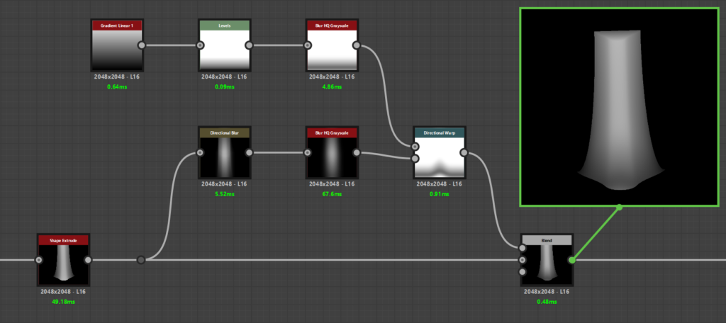
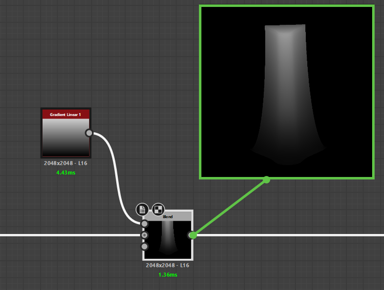
Next, I use the Gradient Linear 1 node combined with the Directional Warp node to push the bottom end of the shape down and warp around the bottom of the shape nicely.
Then, I separate the G channel from the Normal map to create height for the edges on both sides of the shape.
Although this is a small detail of the shape, this helps me limit the shapes from being pressed together, making it more natural and giving my shape a slight bevel on the two sides.
Using the method above, I create two different sets of “scale” shapes. You can create more just by changing the parameters.
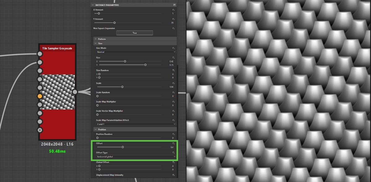
For the tiling, I use the Tile Sampler Grayscale node. A kind reminder here is that, for the Tile Sampler Grayscale node, in the Position Offset section, I set it to 4, and for Offset Type, I change back to the horizontal global option.
This is to ensure my single shapes will be positioned diagonally and overlapping each other.
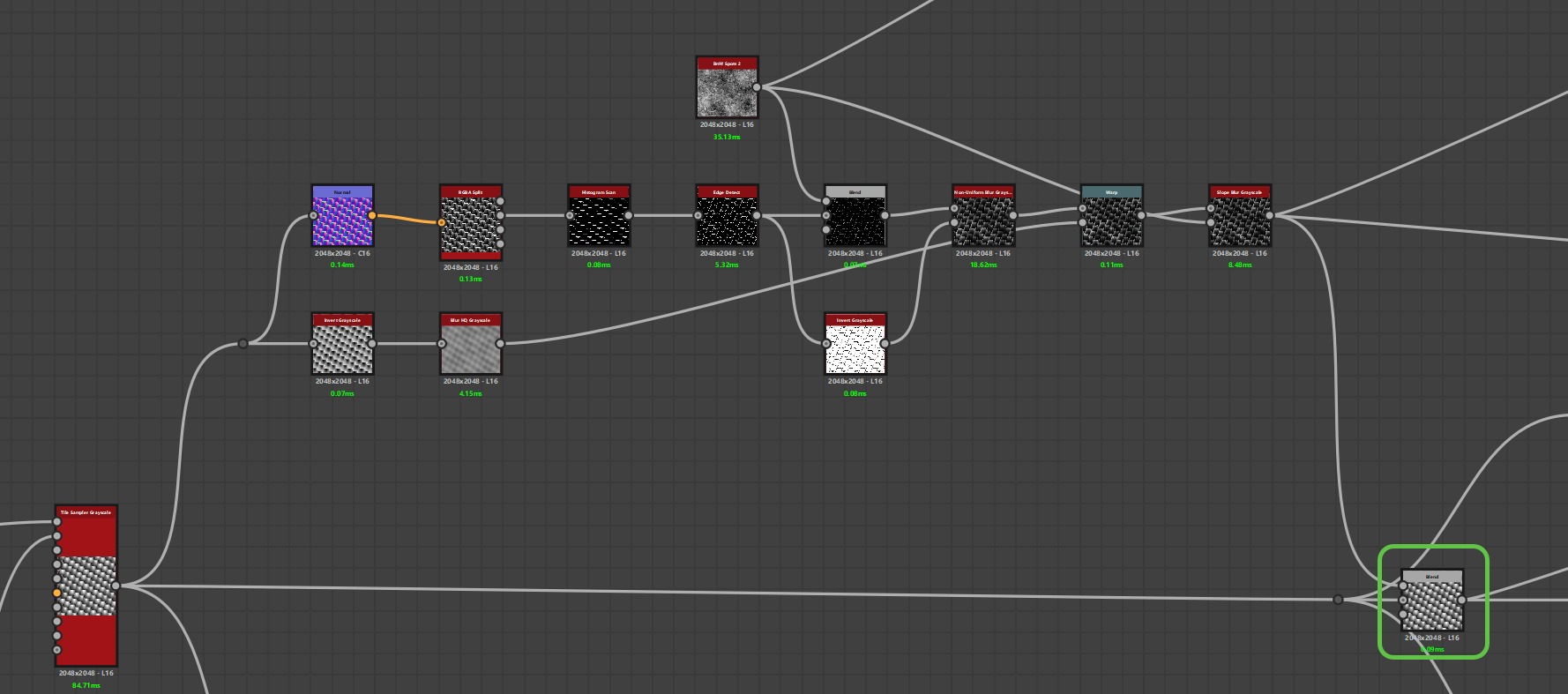
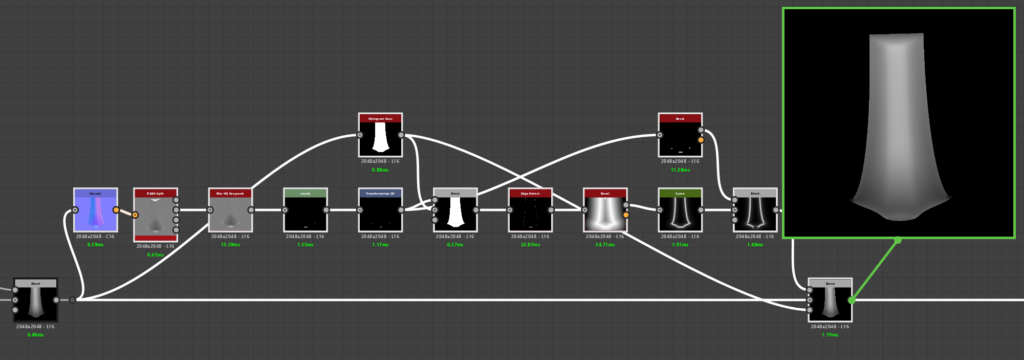
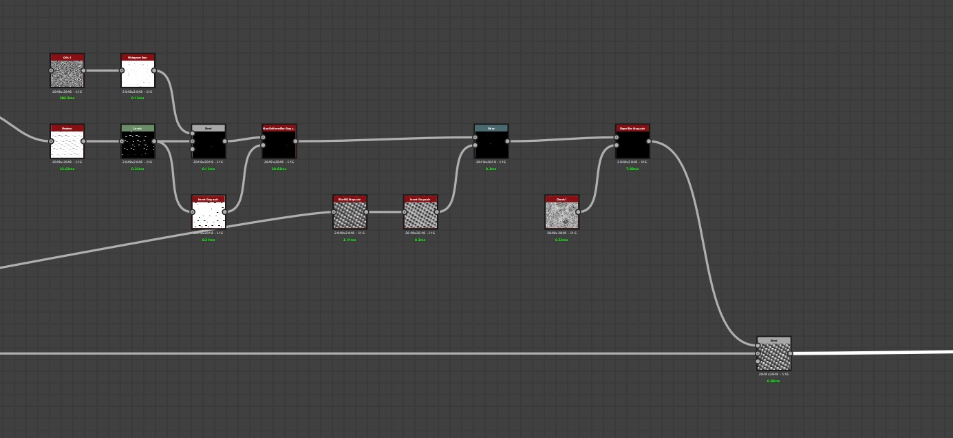
After I have the desired number of tiling shapes, I will start with the details. I would call this the Damage_01 part for short.
I take the normal map of the tiling shape to use with the RGBA Split node to separate the normal channel using the G channel to create a mask.
Then, an Edge Detect node combined with BnW Spots 2 noise to create a flowing effect from top to bottom, then blend it with the tiling shape with the Blending Mode as Subtract.
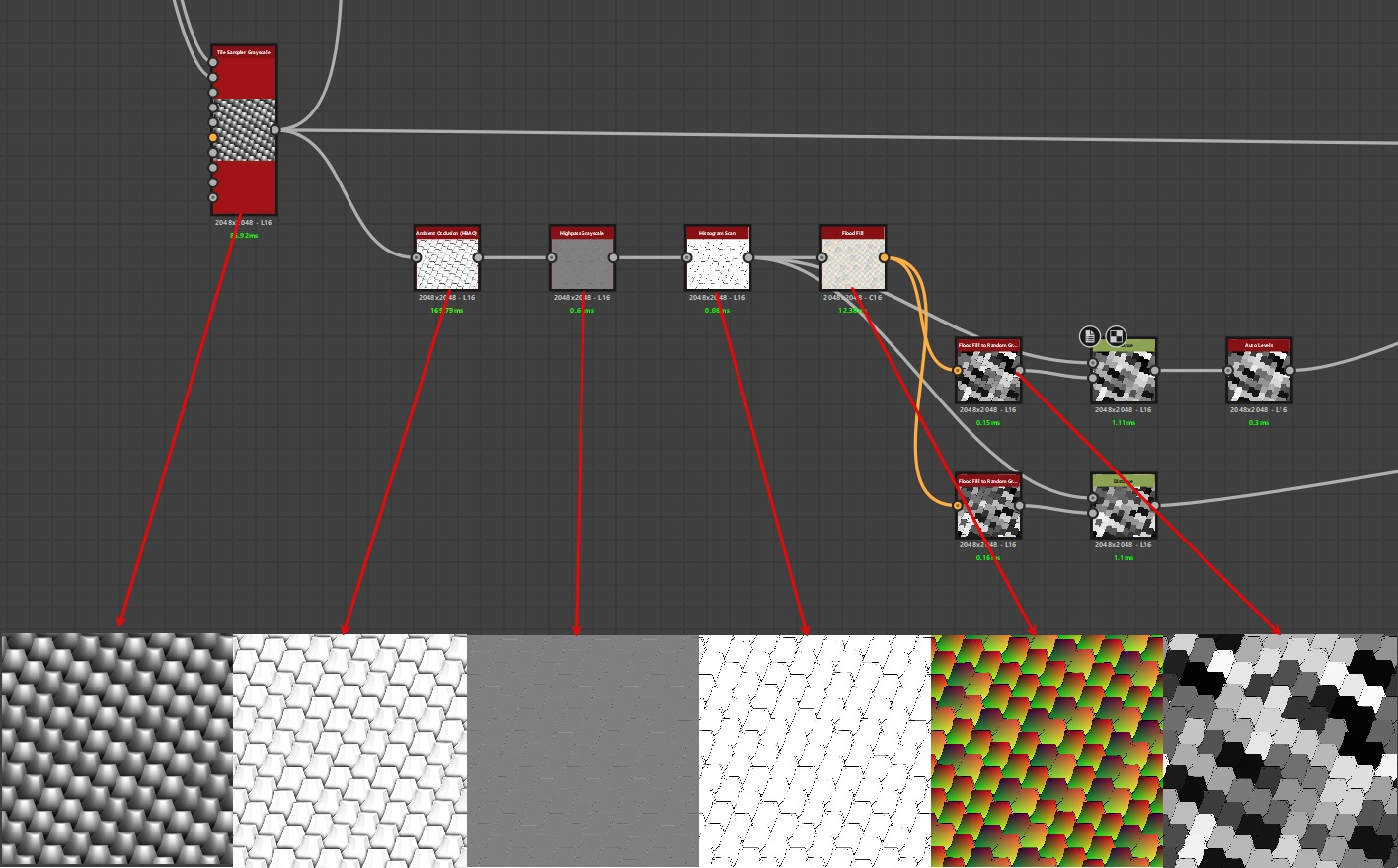
Before I start with Damage_02, I create a cluster of nodes to be able to create the mask for randomness.
The 3 nodes in order are Ambient Occlusion, Highpass Grayscale, and Histogram Scan.
Those nodes help me to get the outline of the tiling shapes.
After that, the outlines are ready to be plugged into Flood Fill, and Flood Fill to Random Grayscale node to be able to create those random masks.
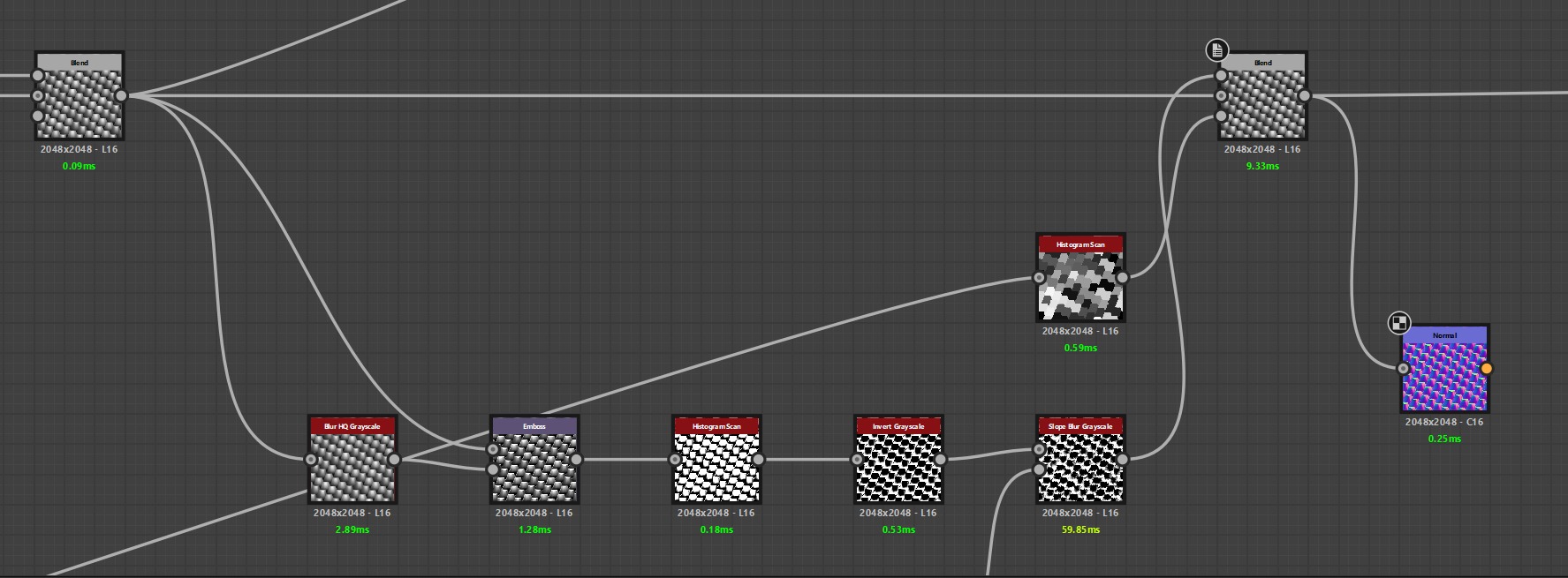
In the Damage_02 part, the cluster of nodes I combined is quite simple. The highlight node here is the Emboss node.
The main reason I used this node here is that it helps me to adjust the high and low contrast flexibly.
Moreover, I can adjust their direction, and I can easily create damage for the lower part of the shape.
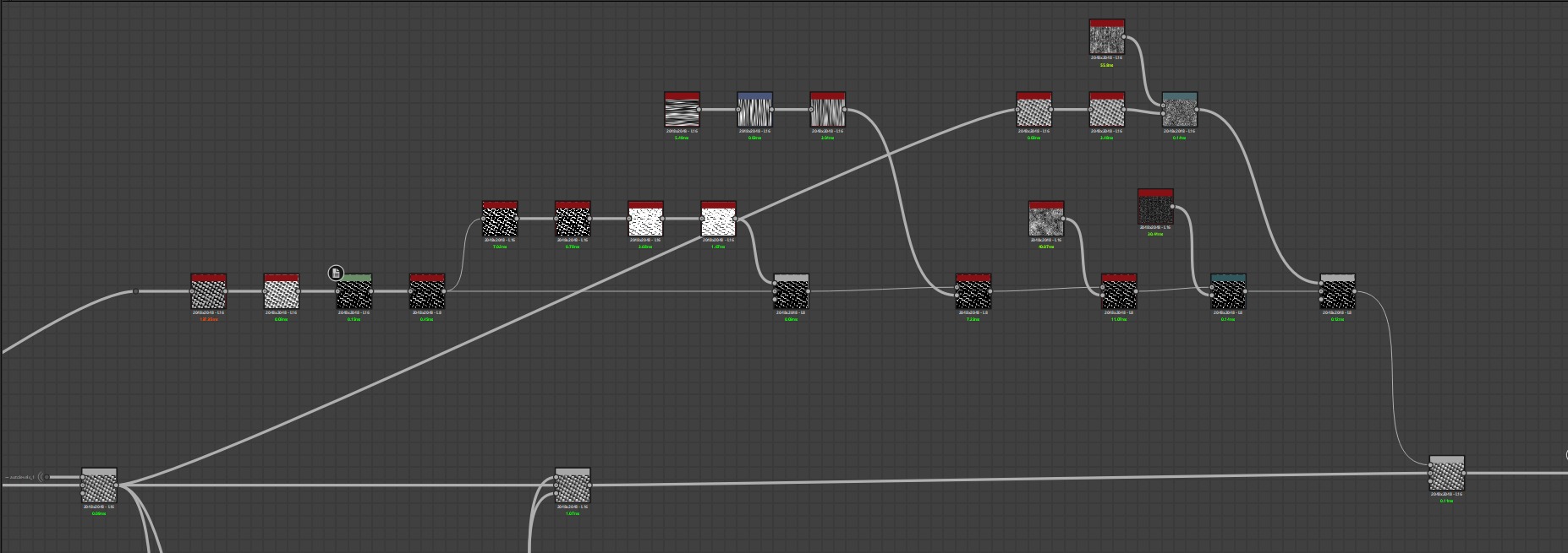
For the next part, the outer shell, we still start from the original tiling shape.
To separate the lowest part of the tiling shape, I use an Ambient Occlusion node.
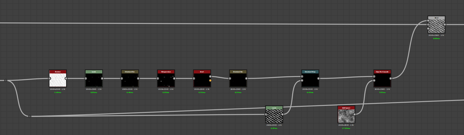
I increase the Ambient Occlusion parameter quite high.
This ensures that the lowest part is completely dark and has a gradual transition to the highest part.
Next, I invert it to get a mask. Then, I adjust the levels to remove unnecessary positions.
Here, I use the Quantize Grayscale node. This node divides the transition level of the mask into several layers.
The top layer will be the brightest layer, adjustable through the node parameters. At this point, I have obtained the mask for the position of the outer shell.
Next, I add damage to the outer shell. I also add noises to make it more natural.
Finally, I blend it with my main tiling shape with blending mode Max (Lighten).
This ensures that the outer shell will have the lowest value and increase gradually.
This 2-node combination is to show the man-made cuts and the cracks commonly found on palm trunks.
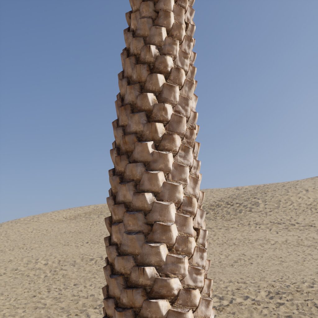
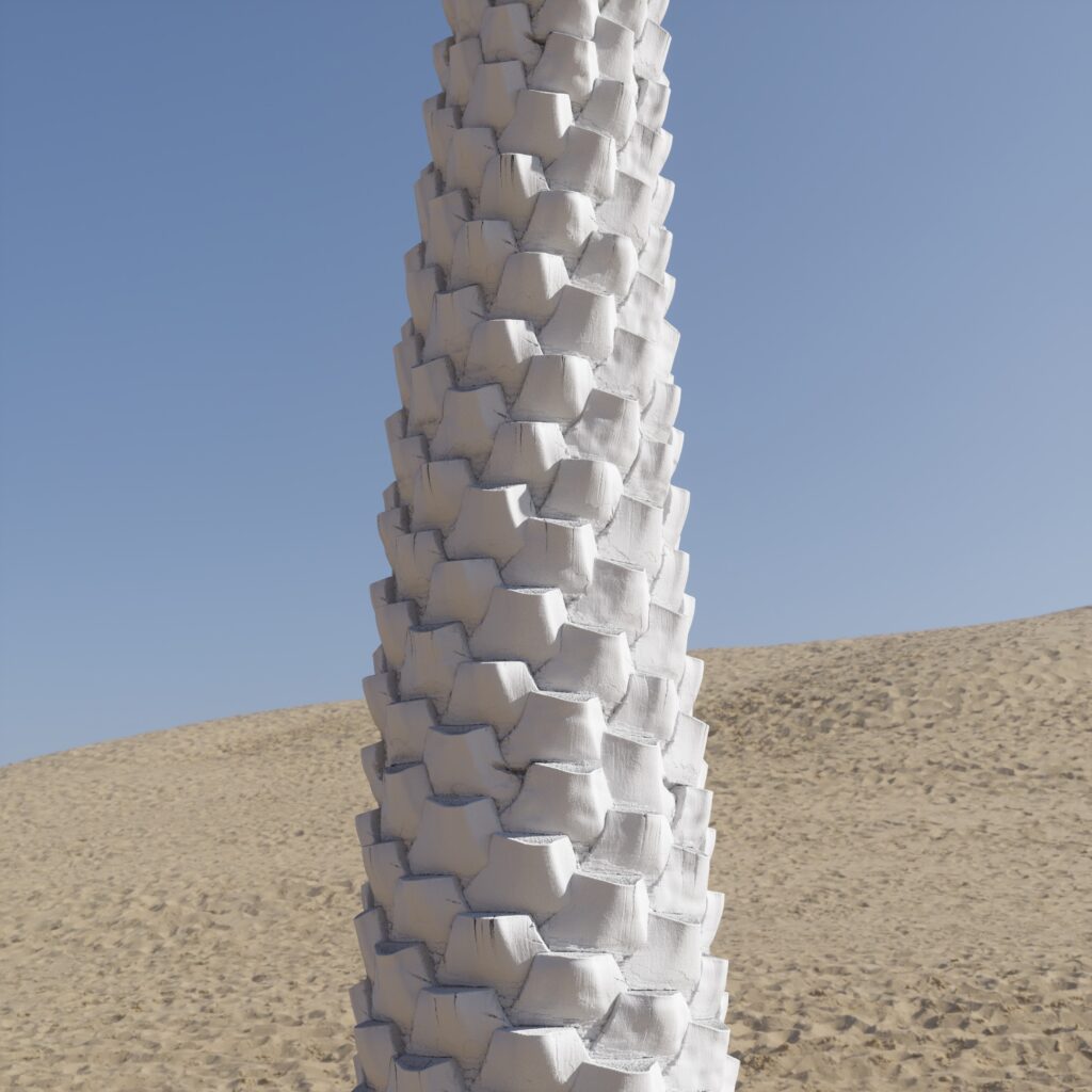
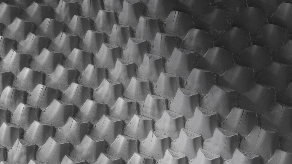
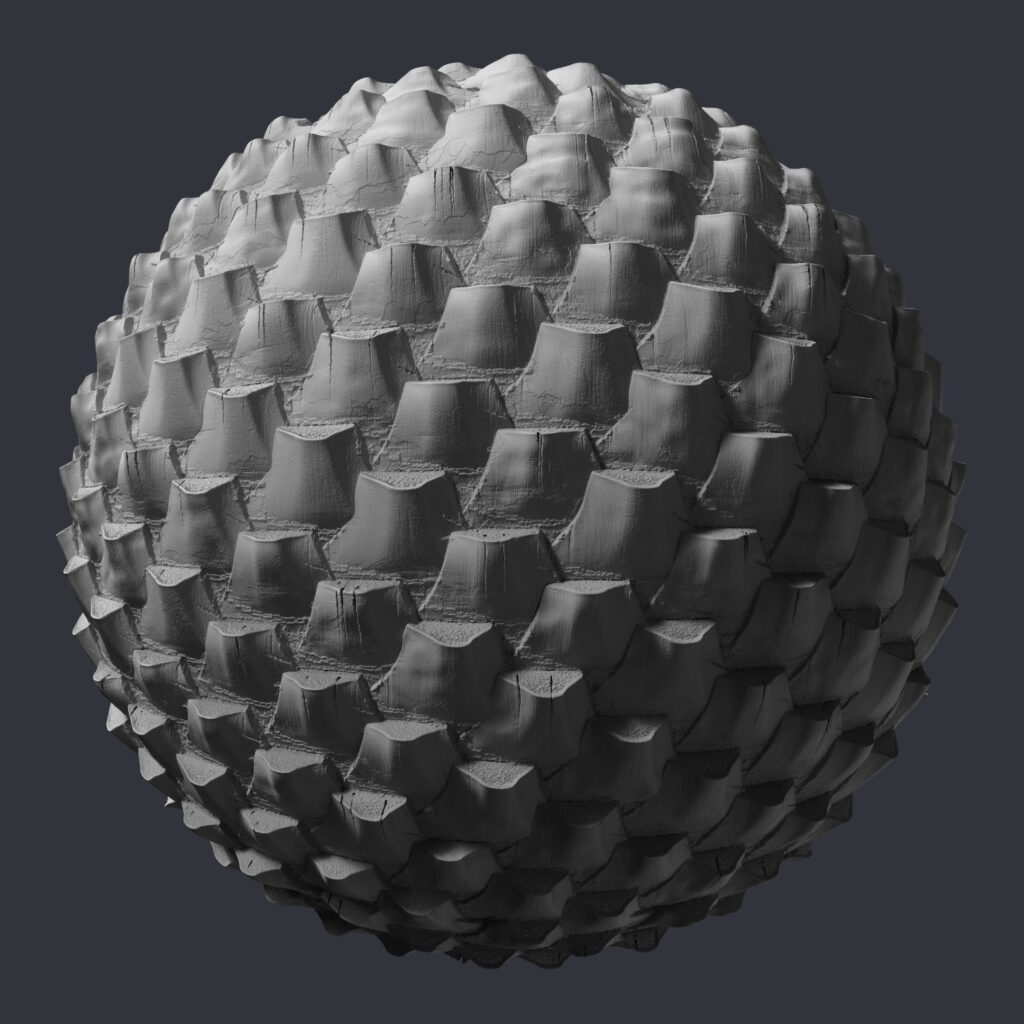
This is the 3D result of the height map upon completion.
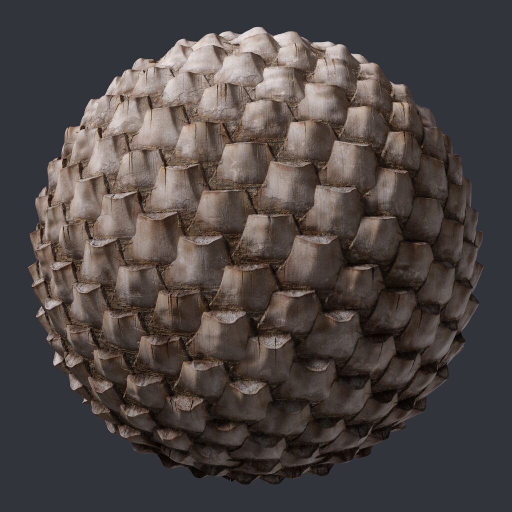
Coloring
When choosing the color for the palm, I compare it with the main reference image, paying special attention to the contrast level.
I often choose colors with different shades to highlight the parts of the tree. This helps the viewer easily recognize its shape and structures.
I take advantage of the mask of each part when creating the height map to mask the color. In this way, I can control the exact position and influence of each color layer.
It also helps create smoother and more natural color transitions.
Then, we will work on the color of the cracks and cuts. I want these points to show the mark of time, so I will choose a darker tone than the general base color of the trunk.
Roughness
For the roughness, I start with the base range with relatively dark color tones. By starting with a darker grey, I will have more room when gradually lightening the color range.
With a similar approach when creating the color, I reuse the masks in the process of height map creation and combine them with the color range of the material that I have completed.
Taking into consideration the size of different details, I create the rough from the largest to smallest, and adjust so that the details in the lowest positions will be the brightest, making them the roughest.
Acknowledgements
Thank you for taking the time to read this article of mine. I am really happy to have the opportunity to share my workflow with everyone. I hope this sharing will assist you in your art creation process.
I made this palm tree trunk post in 2022 using Adobe Substance 3D Designer. Currently, the software has been updated with many new nodes, in turn shortening the process by some more optimizations.
However, I still hope this sharing is useful, especially for those who are new and getting to dig into Substance 3D Designer.
You can download the palm tree trunk material at www.textures.com with this link.
Lastly, wishing you all success and impressive 3D works! Don’t forget to share your creations with others!
Read more articles
You might also like these articles.