Ma Deuce

Introduction
Hello everyone, my name is Aris Chrysikopoulos, and I have been working professionally as a 3D Environment/Hard Surface Artist in the gaming industry for the last 6 years.


Goals
I have mainly worked on sci-fi-related projects, but I have always wanted to create a WW2 project. Through this project, I aimed to learn new software and methods while striving to make it look as realistic as possible.
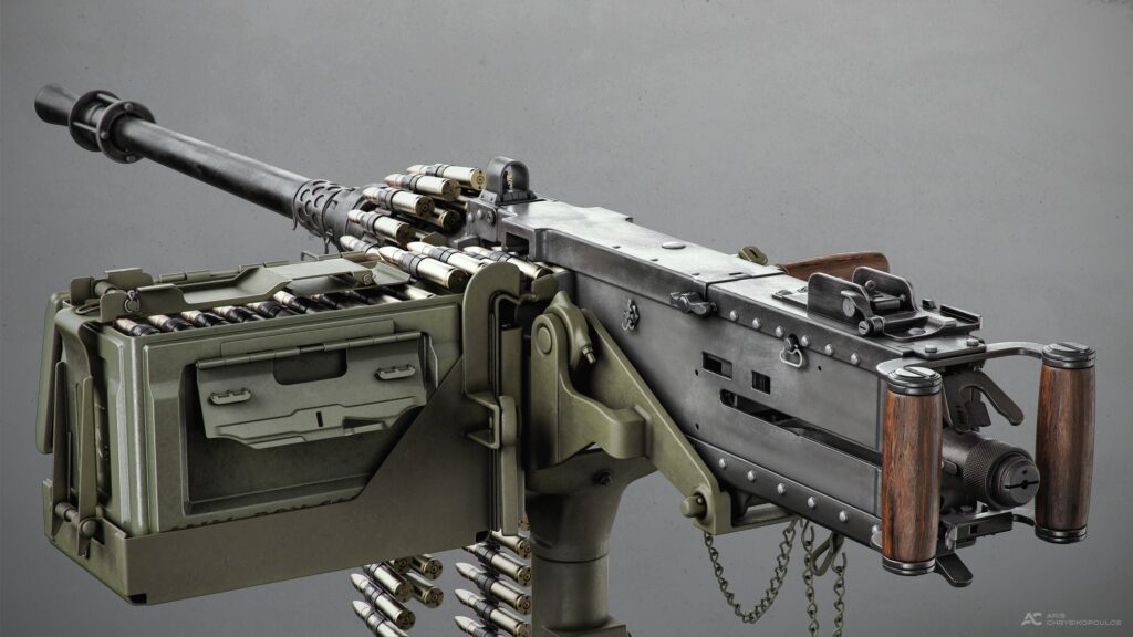
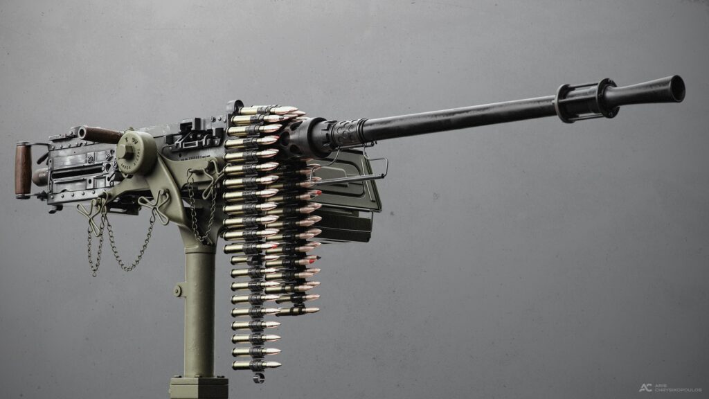
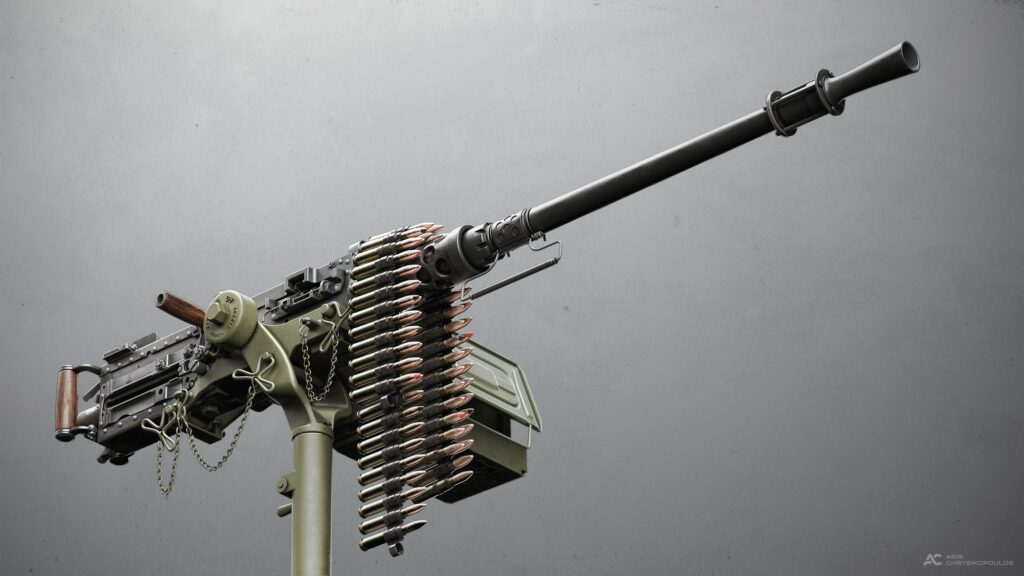
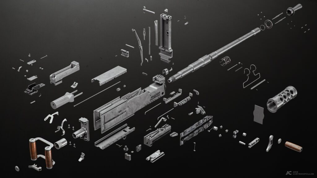
Ma Deuce (M2 Browning .50 Cal) is one of the main components of this project and undoubtedly the most complex. With this article, I will guide you from start to finish, beginning with the process of collecting references and concluding with how I used Photoshop to finalize my renders.
I would like to express my gratitude to my good friend Sergejs Karpovs for sharing his knowledge with me throughout this process.
Tools
For this project, I used:
- PureRef
- 3DS Max
- ZBrush
- KeyShot
- Photoshop
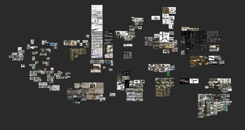
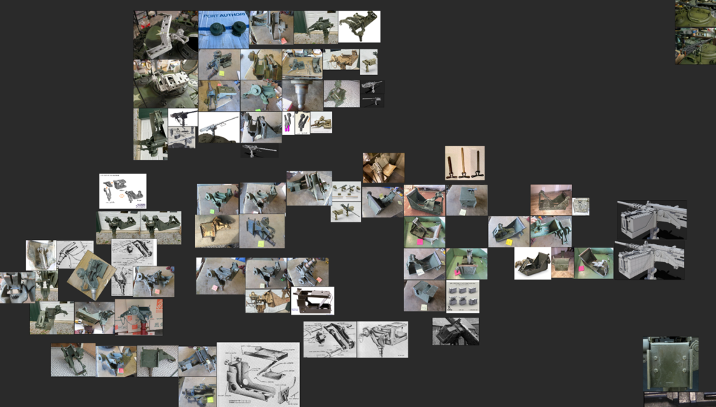
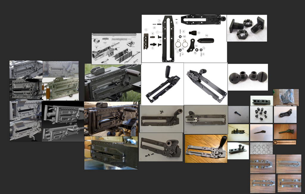
References
For me, it was crucial to find the right specifications and references showcasing all the parts of the machine gun and understanding how everything comes together to make the weapon functional.
Researching and collecting references, which took hours and hours, was the first and most important part before delving into modeling.
My references were gathered from various sources such as Google, online auctions, videos, documentaries on YouTube, articles, miniature modeling forums, and similar projects on Artstation.
A game that greatly aided me in understanding the parts and operation of the actual machine gun is World of Guns: Gun Disassembly.
I highly recommend it for realistic weapon modeling, as it allows you to assemble, disassemble, and view fire and reload animations from a wide range of different guns.
Modelling
I used 3DS Max for my modeling. I began by placing my blueprints and double-checking the dimensions for accuracy by seeking information from other sources such as Wikipedia.
While typically, one would create a blockout of the model, I often prefer to start from the main part and build upon it. In this case, the main part was the side plates, highlighted below with a blue material.
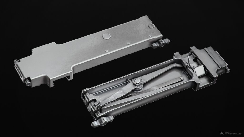
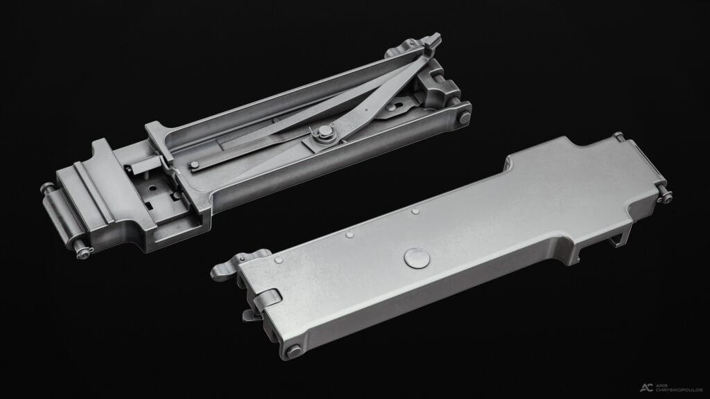
Then, I proceeded to work on other main parts sitting on it, such as the cover. The cover piece, highlighted with the green material, contains many small hidden parts.
To maintain a clean scene, I created an instance of it and worked on it separately. Building all the smaller parts, highlighted with the red material, as individual objects made the process easier.
Once I finished this part, I parented all the small details to my cover’s instance and then snapped them back to the main cover piece.
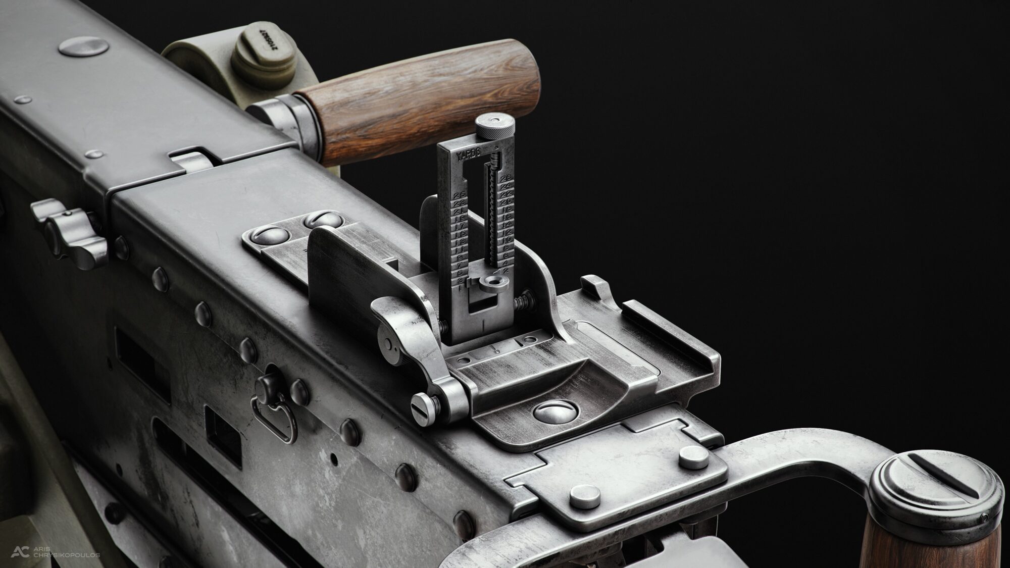
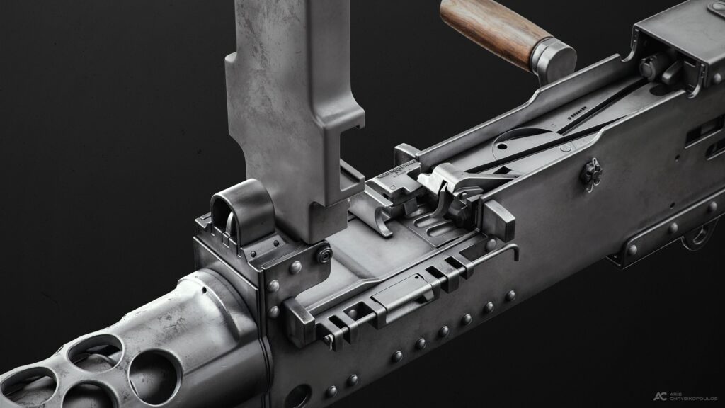
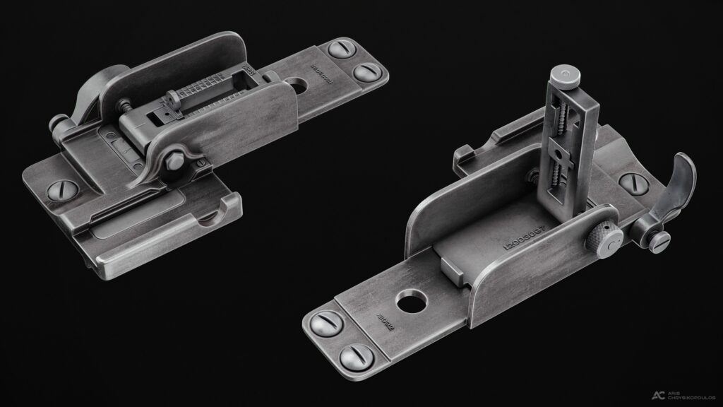
This process was similar for other large parts which had many smaller ones attached, such as the bracket, the grip, and the rear sight.

TIP:
It’s always a good idea to keep in mind how much detail you want to show on your final renders and how your model is going to look in close-up renders.
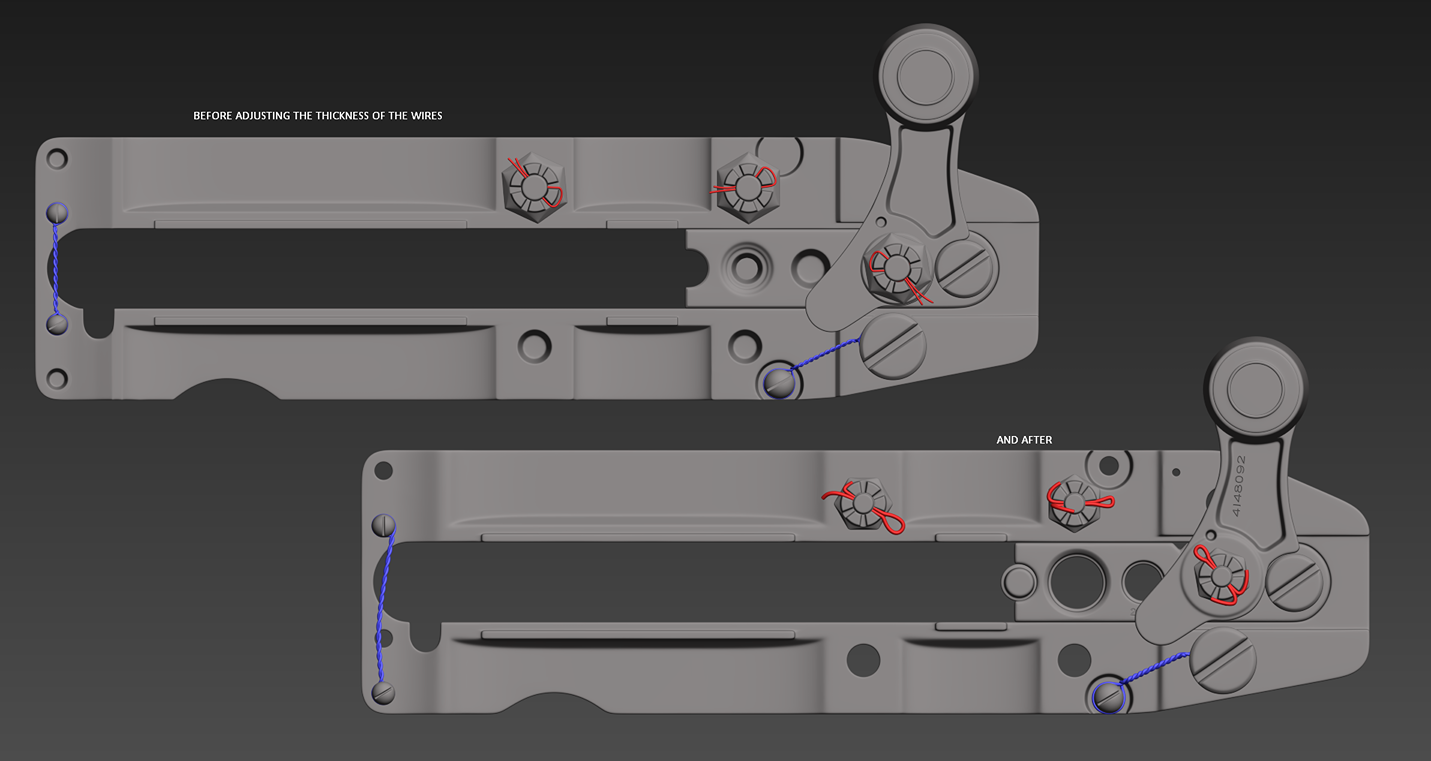
Although I was aiming to make everything as close to the real thing as possible, I had to scale up some small parts such as wires and pins to avoid having them pixelated on my final renders.
For heavy Boolean operations, I decided to use ZBrush as 3DS Max can’t handle them very well.
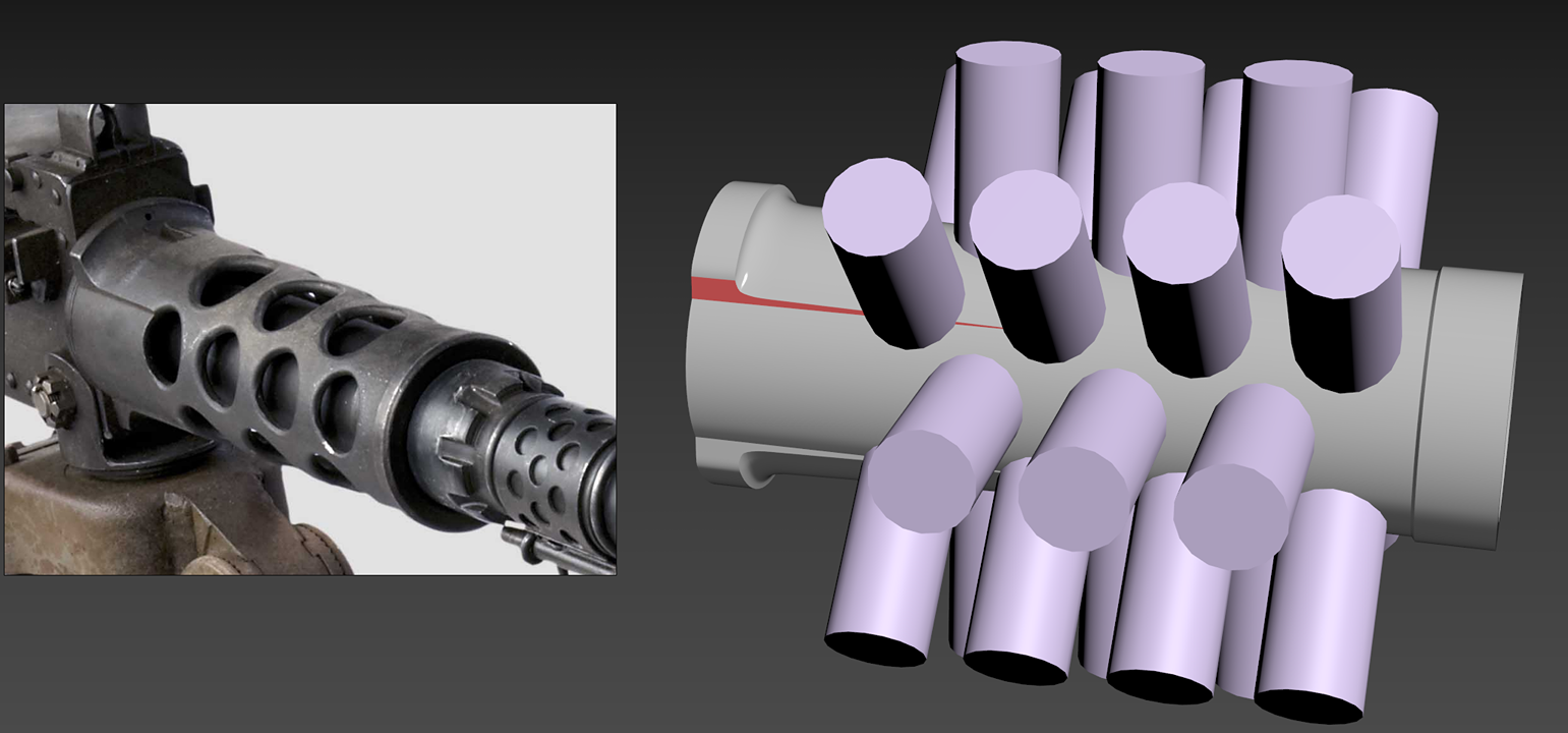
A good example of this process would be the barrel support. After creating the main silhouette of the barrel support in 3DS Max, I added the cylinders as separate objects which I intended to subtract in ZBrush to create the holes.
I had to ensure that shape details, such as the one highlighted in red below, were preserved throughout the process.
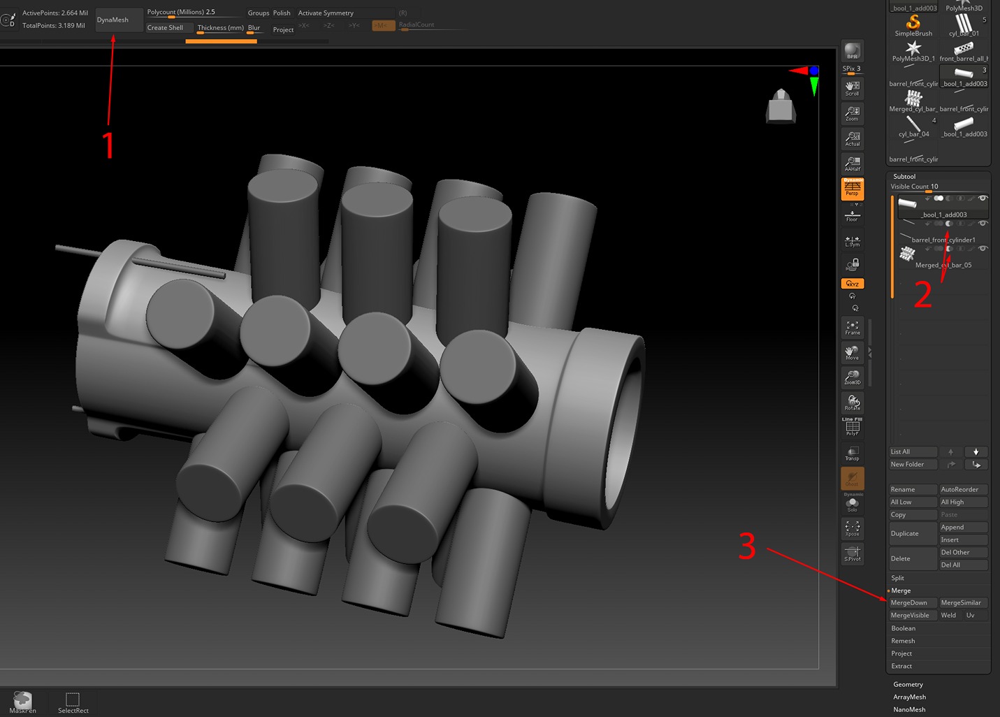
In ZBrush, after subdividing my pieces, I dynameshed them (1) and then set my cylinder pieces for subtraction in the toolbar (2). The order in which you perform these steps doesn’t matter.
I ensured that my main silhouette was on top of my list, and then I merged down twice (3). ReDynamesh after each merge to ensure that the Booleans are applied correctly.
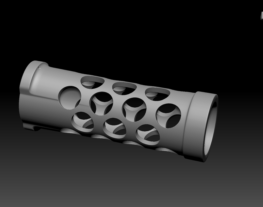
And here it is after the final Dynamesh.
TIP: I would suggest always making duplicates of your subtools, especially before dynameshing, to be able to go back in case it is needed.
Also, after dynameshing a mesh, there is a good chance that some of the details can disappear or some edges get distorted, even if the polycount is set to millions.
In that case, we can project the details of the original mesh that we duplicated before dynameshing onto the dynameshed mesh.
The process is pretty much the same for all the other parts, using each of the software where needed for the best results.
TIP: To avoid any funny business, before importing your assets to ZBrush, always make sure:
- That you don’t have any ngons.
- That your geometry doesn’t have any holes.
- That your normals are correct.
- To apply transforms to your objects (reset XForms for 3DS Max).
Polishing
After completing all the pieces, I imported them into ZBrush for polishing. I aimed to smooth and refine the edges around my model, which is a straightforward process.
This step helped ensure a more consistent final result during rendering and will lead to better outcomes when baking the model down for game assets.
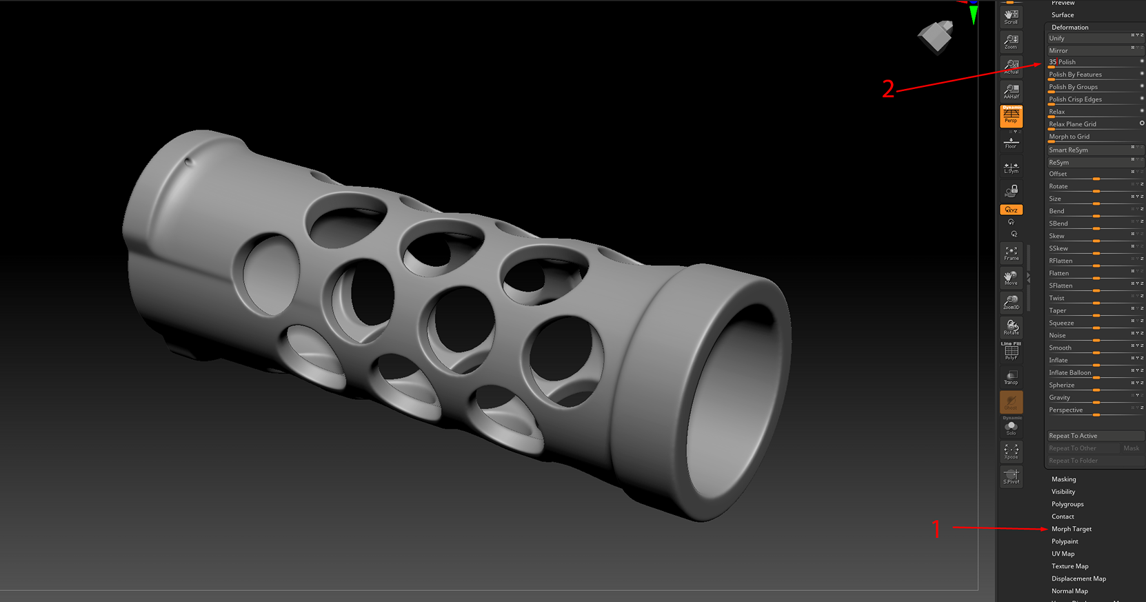
Before beginning the polishing process, I selected ‘Store MT’ under the Morph Target option in ZBrush (1). Then, I proceeded to polish the model (2).
The amount of polishing depends on which achieves the desired results. With the Morph Brush, I can always bring back any details I want to keep crisp.
I highly recommend watching the following video on YouTube which gets more in-depth on how to use ZBrush for high-poly weapons:
Official ZBrush Summit Presentation: Red Storm Entertainment.
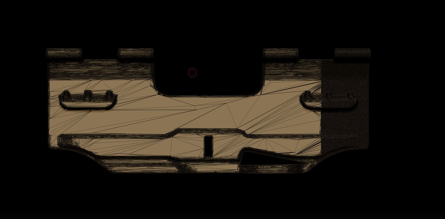
Before exporting my meshes from ZBrush, I had to decimate them to reduce the polygon count of my models. It seems that ZBrush doesn’t handle decimating hard surfaces well.
The following image shows a good example of what I mean (this occurred quite a few times while decimating various parts of my machine gun).
I tried to figure out what was causing this issue by doing research and discussing it with colleagues. Unfortunately, it seemed like there wasn’t a proper solution available.
After experimenting, I found a workaround to fix these kinds of issues. Before decimating, I applied a tiny amount of noise to my subtool, polished it a little bit (using values 2-3 worked for me), and then attempted to decimate it again.
Magically, after two or three attempts with different noise values, this method worked perfectly for me, without any shading issues.
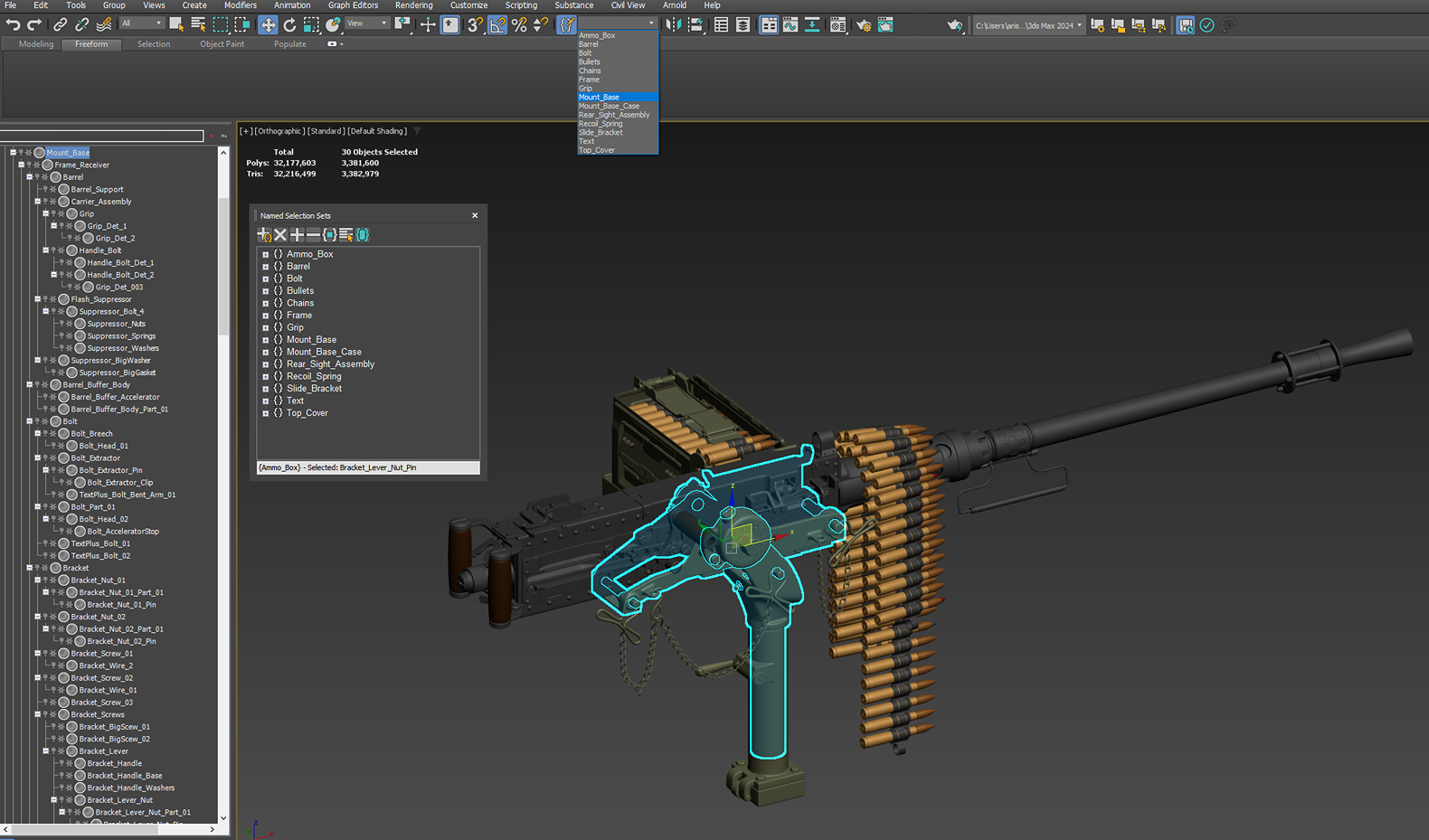
After reimporting everything into 3DS Max, I needed to tidy up my scene. I prefer to keep my modeling files as clean as possible.
Therefore, before importing my model into KeyShot, I ensured they had proper naming, adjusted hierarchies, and created selection sets.
The next steps were to import all the Ma Deuce’s parts into KeyShot, set up some lights, and create/apply materials.
Setting Materials and Rendering
In my case, since Ma Deuce is a high-poly model, I didn’t have to worry about UV mapping, as I utilized material projection in KeyShot. Of course, with this workflow, texturing can’t be as precise as hand-painting, but it can produce very fast and decent results.
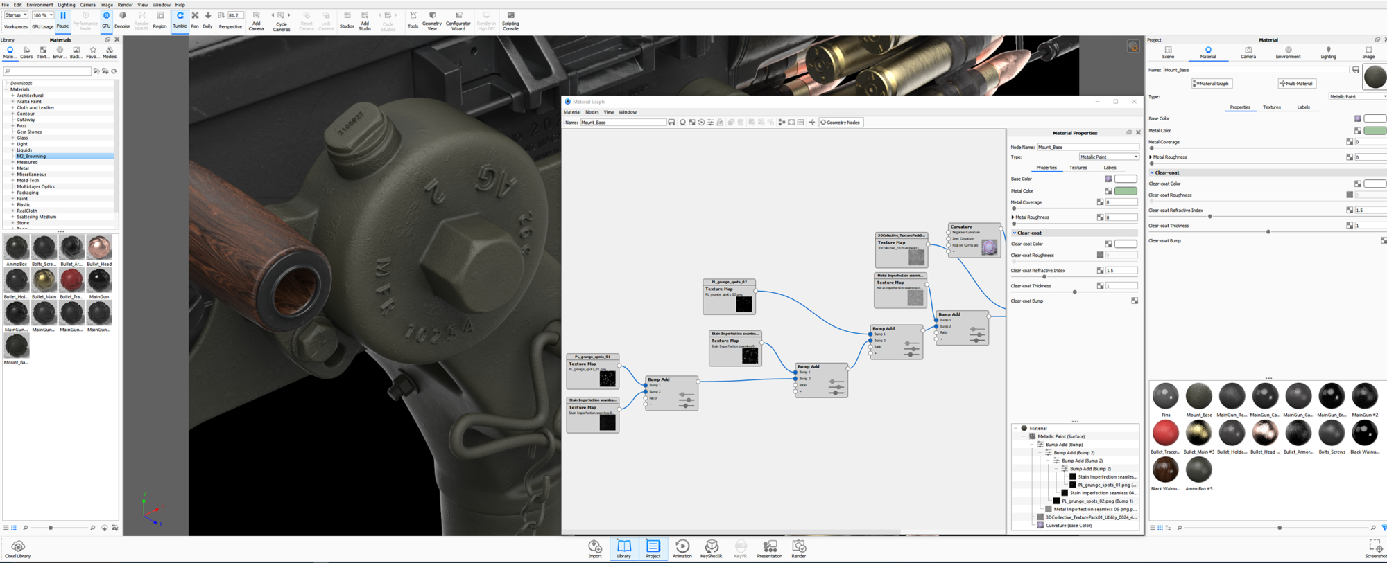
I aimed to create as realistic materials as possible using the Material Graph for each part of my model. To achieve this, I imported roughness maps into KeyShot, most of which I purchased from Artstation while some others were available as free online.
I recommend building a library with a wide variety of roughness maps, as they are extremely useful. All other setups and tweaks, such as mapping type, bump, roughness, etc, were adjusted within KeyShot’s Material Graph.
After testing different combinations of roughness maps, I reached the results that I found most acceptable for my goals.
Lighting
After setting the materials, I started positioning my cameras. Each camera had its environment/lighting setup depending on the camera’s angle.
For the lighting, I opted for the three-point lighting (Key Light, Fill Light, Back Light), and I added more lighting as needed, wherever I felt that interesting spots were highlighted or nice reflections and shadows were created.
Although I tried to maintain consistency in lighting between shots as much as possible, I didn’t worry too much since I could adjust almost everything later by post-processing my renders in Photoshop.
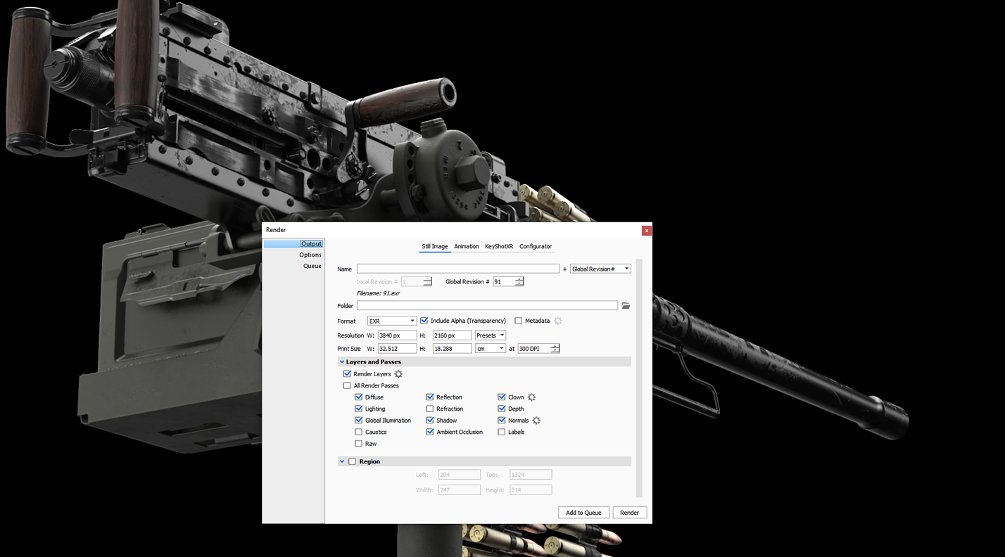
To achieve this, I made sure to export the render layers that I needed from KeyShot so I could tweak them later in Photoshop. (There is an option in KeyShot to export the layers as one multi-layer file, but I decided to export each layer as its file.)
Make sure to export your files to EXR format. Even if you’re not using Photoshop, EXR files provide accurate and reliable color representation and allow for multiple channels of color and image data, such as alpha channels or metadata, to be stored in a single file.
Additionally, EXR files are much smaller compared to PSD files.
If you are not familiar with KeyShot’s Material Graph and rendering, I would recommend watching the following videos:
Post Processing
During the post-processing stage, I learned many new techniques, and I would like to share them and guide you through the entire process.
After one of my renders finished, I imported all the render’s layers into a stack in Photoshop.
I will use one of my renders as an example to demonstrate this stage.
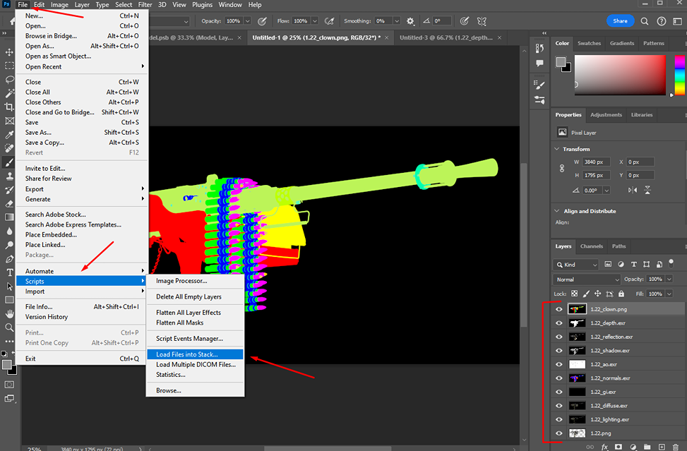
As my EXR files are set to 32 bits/channel, I couldn’t make any edits. Therefore, I made sure to change them to 8 bits/channel. For the depth and GI (Global Illumination) files, I had to make this change separately as I had more tweaks to do.
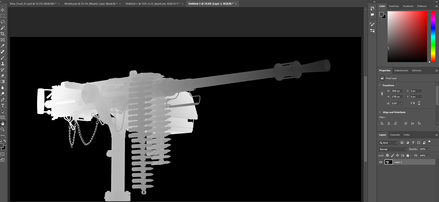
For example, when I opened the depth file in Photoshop, it initially appeared white, but I made adjustments to it.

When setting the mode to 8 bits/channel, I chose to merge layers before adjusting the depth. Then, I selected the equalized histogram method, which allowed me to create an alpha channel for the depth layer.
This approach worked well for me. Now, I could utilize this pass for depth of field, enabling one area of my machine gun to appear lighter and another darker, depending on which area looked more interesting and had more details.
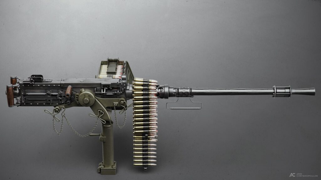
In this render, the barrel was the least interesting part.
I did the same for the GI layer, for this I just merged it and then kept the Local Adaptation method.
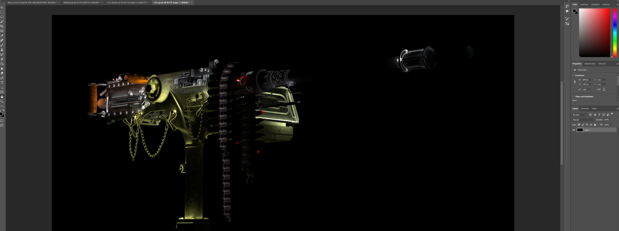
I used the render layers as my basic layers. I went through different adjustments, blending methods, filters, etc, as needed until I achieved my desired result.
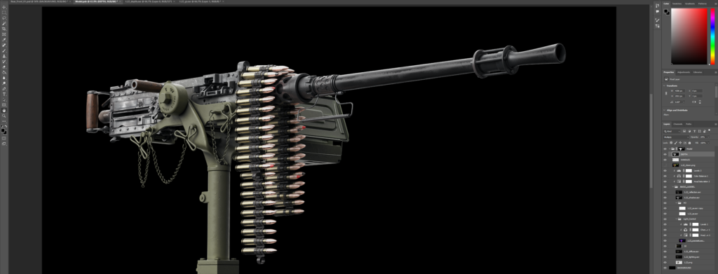
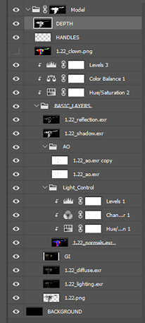
The hierarchy of my layers in the screenshot above represents the final arrangement, but I didn’t edit them in the same order as shown, which is as follows:
- Before starting the layer editing process, I added a background layer with a black color and grouped all my basic layers. I masked the group by using 1.22.png as a mask.
- Then, I placed the 1.22.png layer as the base layer. All the other layers were placed on top of this base layer. -After that, I edited the AO layer. The AO layer should always be set to ‘Multiply’. If you find that the ambient occlusion is insufficient, you can always duplicate that layer as I did. -I continued with the Depth layer. I used the ‘Multiply’ blending method.
- The next step was the Diffuse layer, which allowed me to enhance the colors. I ended up using ‘Overlay’.
- Then, I worked on the GI layer, which can add some nice light bouncing effects to the model and additional colors depending on the materials’ diffuse color. For the GI layer, I used ‘Overlay’. -Afterwards, I edited the Lighting layer. The Lighting pass adjusts the brightness and darkness of the model, depending on the materials’ diffuse color. I used ‘Color Dodge’ because it lightens the colors more while reducing the contrast.
- Next, I worked on the Normals layer; with this, you can control the lighting and rework it quickly without having to rerender your model. By default, it looked like the following:
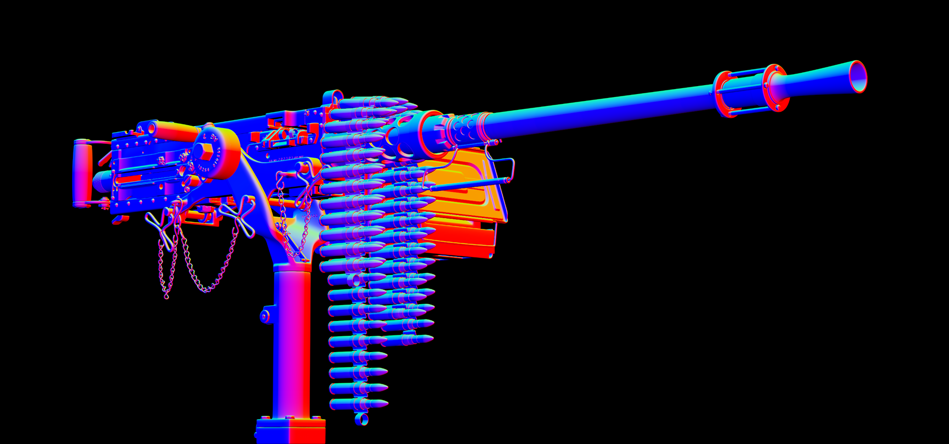
To achieve the desired effect, I had to make several adjustments. First, I added a Hue/Saturation adjustment layer directly to Normals, followed by a Channel Mixer where I selected the Monochrome option.
I grouped these layers together and experimented with different blending modes until I found that ‘Color Dodge’ was the closest to what I wanted.
Additionally, I applied a Levels adjustment layer to sharpen the lighting and highlight the silhouette of my M2 Browning .50 cal. In the following video, I will demonstrate why the Normals layer is so useful by setting it up for my render example.
- After that, I worked on the Reflection layer. This layer contains the reflections of all reflective materials in the scene. In this case, I used the ‘Soft Light’ blending mode.
- Lastly, I edited the Shadow layer. This layer can be used similarly to the Lighting layer; I preferred to use it with ‘Multiply’ blending mode to make all the shadows darker.
- That concludes the description of the basic layers. The Clown layer helps to mask out parts of the model that we don’t like and tweak them separately.
Now that I finished editing the base layers, I grouped them and I placed some more adjustments attached to this group to tweak the dark and bright values overall and to make my colors more vivid.
I believe that experimentation with blending modes, adjustments, and different opacity values is necessary to achieve the desired results.
The outcome is as follows:
TIP: I would recommend placing the Reflection layer and all the bright layers at the top of your layer stack because they add to the values below them. Generally, be careful not to use values that are too bright or too dark.
Additionally, if you plan to tweak your render or paint over it, ensure that you have completed all layer adjustments first.
Later on, I selected all the base layers and their adjustment layers and converted them to a smart object.
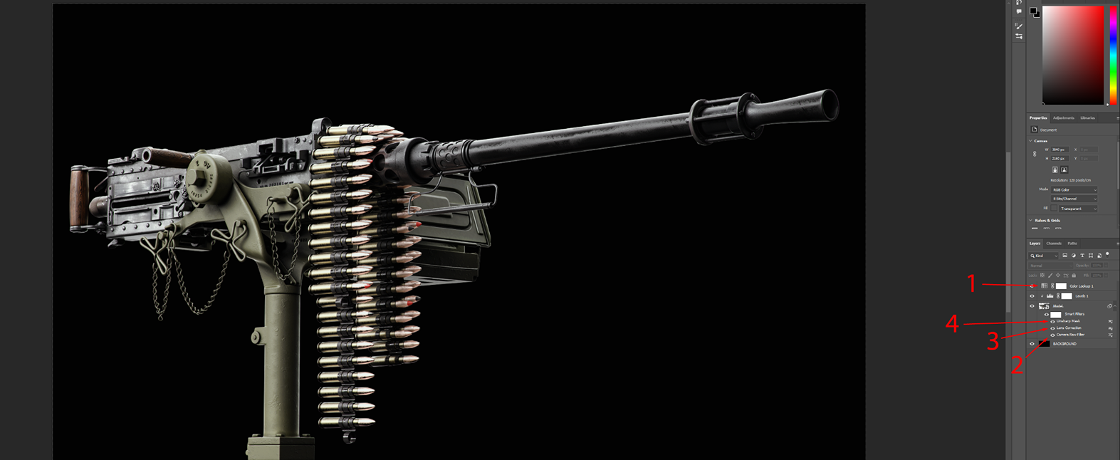
On top of that, I placed a Color Lookup (1): Kodak 5218 Kodak 2383 to add a cinematic effect. However, it’s important not to overdo it while adjusting values.
I applied the Filter, Camera Raw, and adjusted the Dehaze and Clarity (2). Dehaze reduces the haze to make my render cleaner, while Clarity enhances mid tone contrast and sharpens my render.
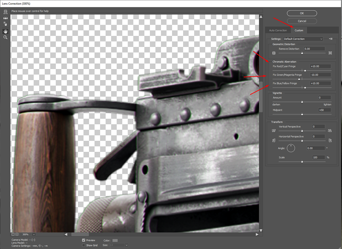
After that, I added another Filter called Lens Correction (3) to introduce a little bit of chromatic aberration around my model’s edges.
Lastly, I used an Unsharp Mask which helped enhance the crispness of the details.
The final step involved adding a background, which was created using a Gradient Fill layer and some roughness maps to enhance its visual appeal.
Above my model’s layers in the stack, I applied some vignette and noise/grain effect layers.
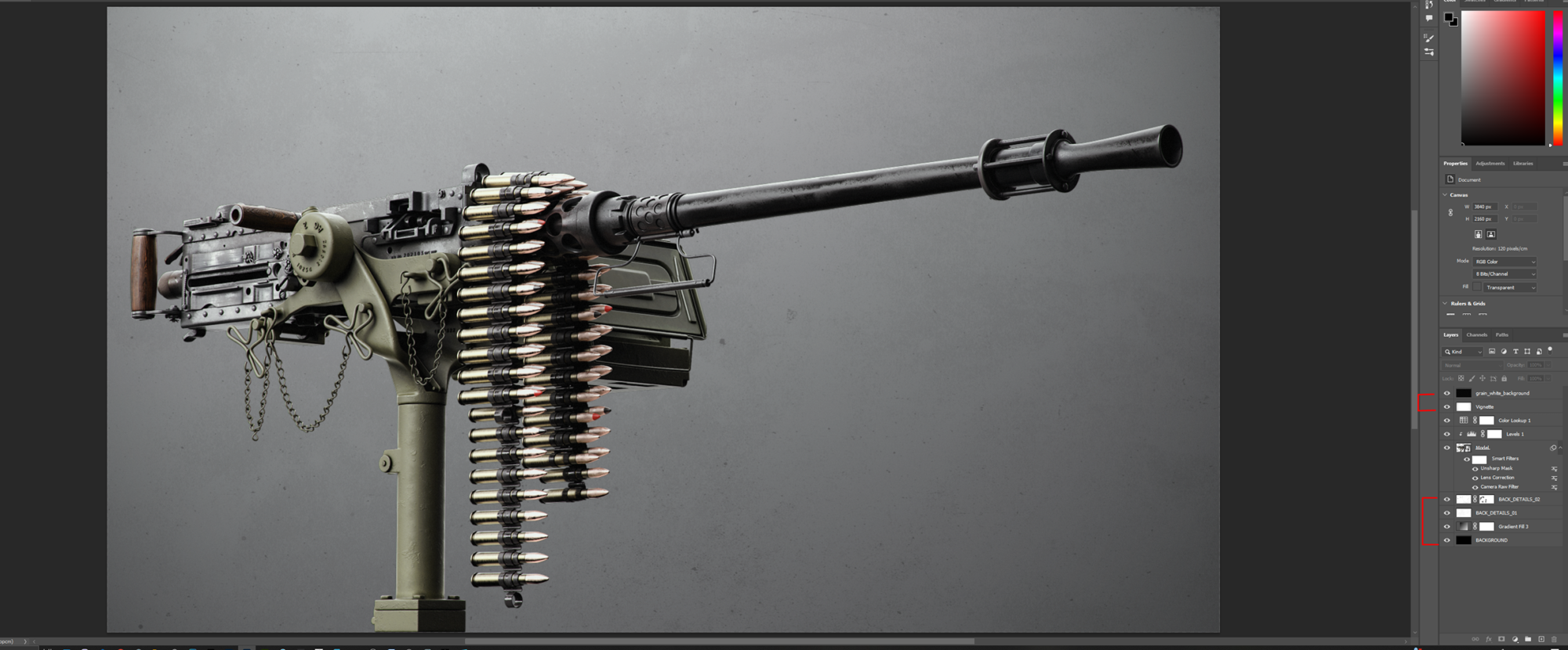
TIP: I recommend avoiding completely black backgrounds in final renders, as brighter backgrounds make it much easier to demonstrate all the details of your models.
If you choose to use a Gradient Fill, try to avoid using a completely black color. If you need to readjust your Gradient Fill’s position, simply select your Gradient Tool.
I also wanted to add some blur, but before that, I needed to select most of my layers and merge them. I would suggest duplicating your document so you always have the unmerged version as a backup. I used Lens Blur and applied my Alpha as a Depth Map Source.
With a Set Focal Point selected, I chose which area of my model I wanted as my main focal point. Then I made some adjustments until I achieved the result that I liked the most.
I will demonstrate to you the above process in the following video:
Conclusion
I am very pleased with the outcome; the entire project was both enjoyable and educational, as I learned a great deal throughout the process.
I am looking forward at some point to baking it down and doing a more realistic texturing pass on it.
I appreciate your time and thank you for reading my article. I hope it was worth your while, and that you found something new and useful for your next projects.
Read more articles
You might also like these articles.