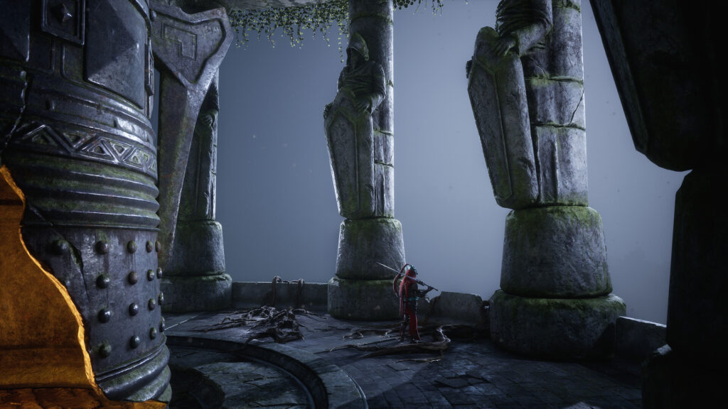
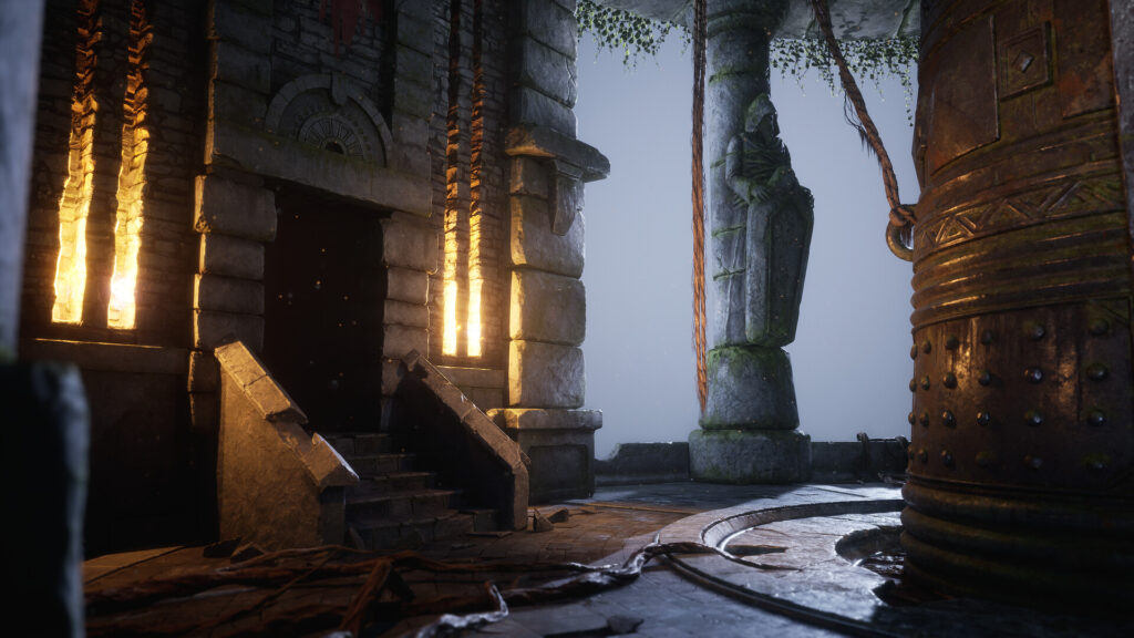
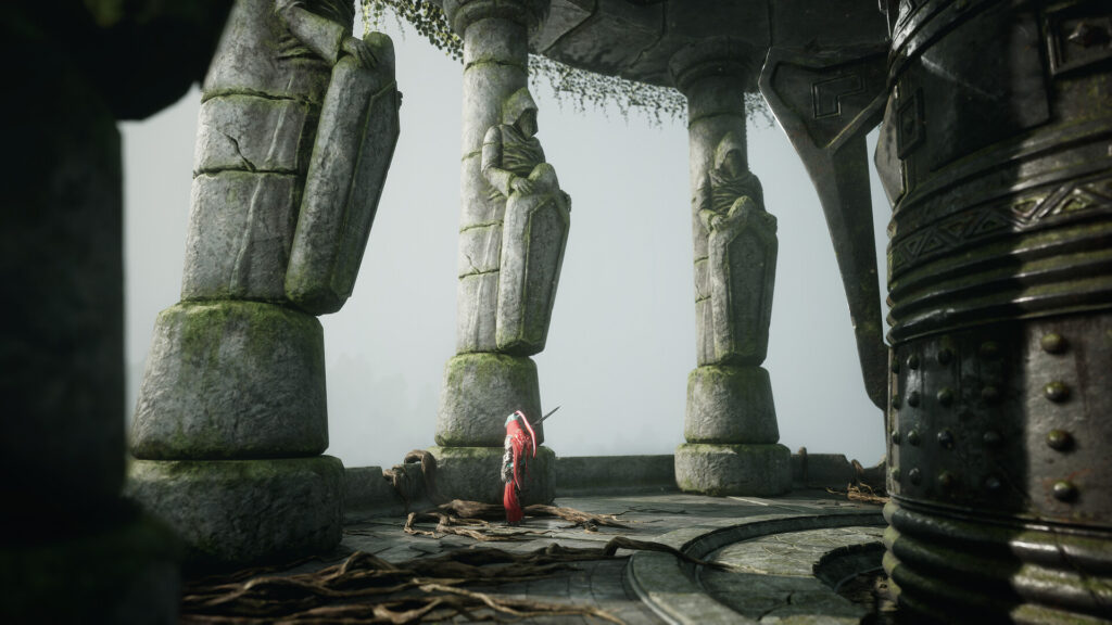
Bell Room

Introduction
Hi everyone! My name is Egor Pasko, I'm 19 years old, and I'm a self-taught 3D Environment Artist. I live in Tbilisi, Georgia.
Currently, I'm working part-time as an Environment Art Manager at Leartes Studios.
However, I'm also actively seeking a full-time job in a game outsourcing or game development studio.
I began learning 3D graphics three years ago, in May 2020, and I decided to pursue my growth in game Environment Art. I am continuously learning new things and improving my skills in modeling, texturing, composition, lighting and more.

Goals
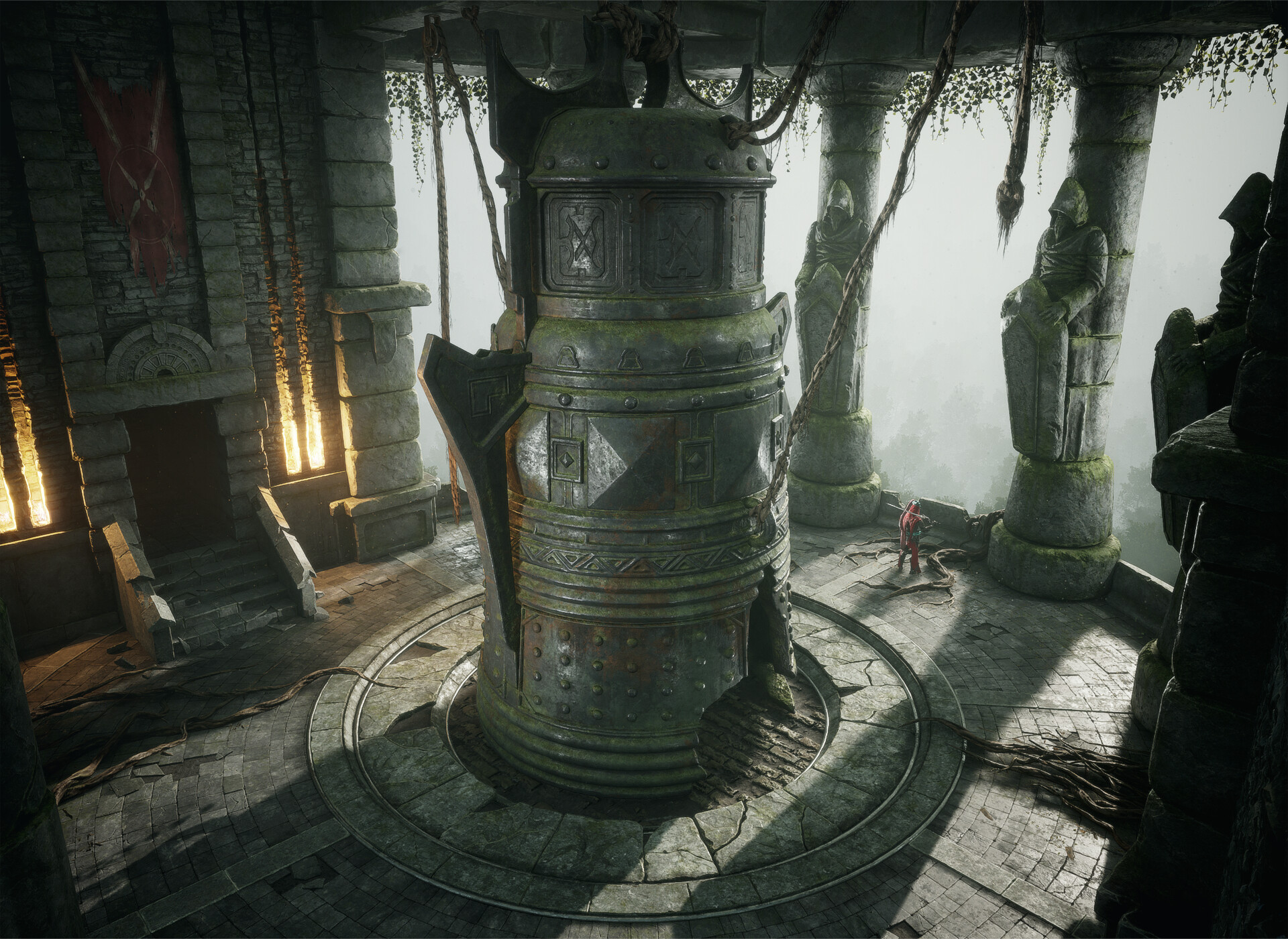
When I started working on this environment, I aimed to improve my sculpting skills and work with two UV masks, lighting, and the overall mood of the environment. My main goal for this project was to create a visually stunning game scene based on the concept, focusing on intricate object details while minimizing the use of unique textures.
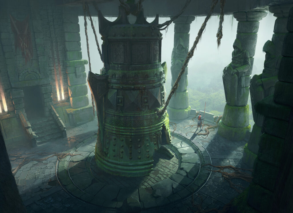
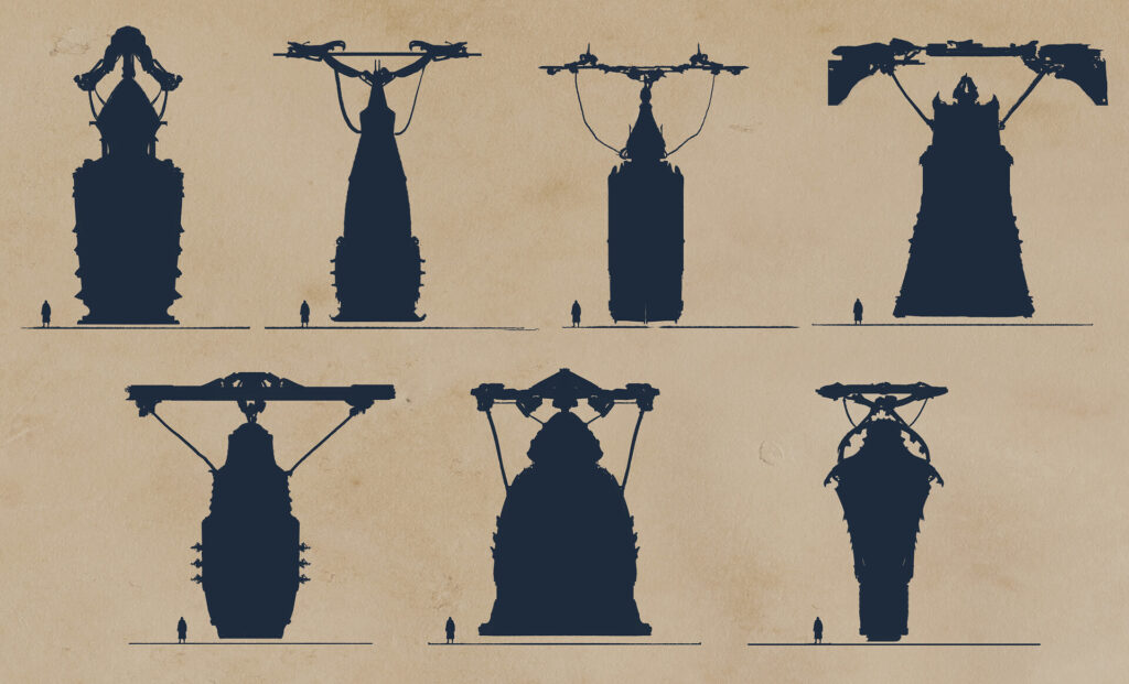
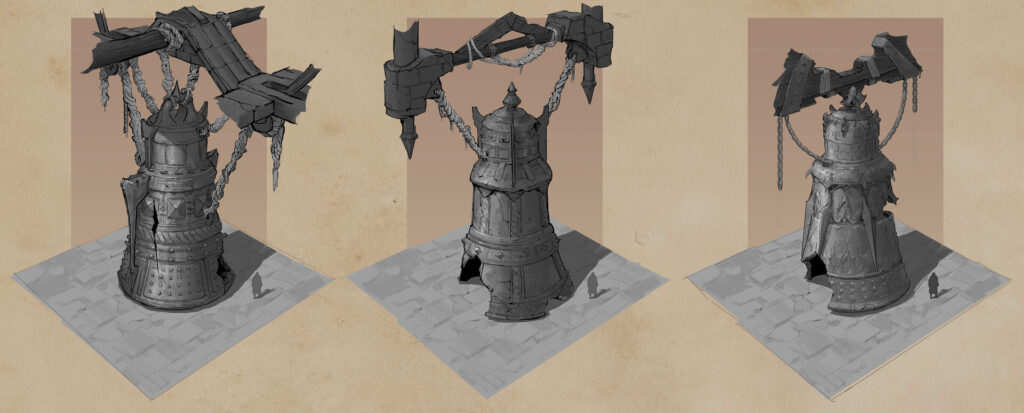
This project is based upon Andrew Palyanov’s concept design of the “Bellroom”.

Software
I used a lot of different software to create this project:
- PureRef – gathering references.
- Autodesk Maya – the main 3D software.
- ZBrush – for High-Poly sculpting and Low-Poly creation.
- RizomUV – for creating UVs in certain cases.
- Marmoset Toolbag 4 – for mesh map baking.
- Substance Painter – for texturing.
- Substance Designer – for creating some tileable materials.
- Quixel Mixer – for quickly creating tileable materials using Megascans.
- Unreal Engine 5 – the game engine that was used for this project.
- SpeedTree – for creating roots.
- Quixel Megascans – for some materials and decals.
- Photoshop – for post-processing and LUT creation.
For some people, it may seem like a lot of software has been used, but in fact, it all depends on preference. Of course, many of these programs can be replaced and removed from the pipeline.
For example, you can make UVs only in Maya. But I like to learn new tools that help me achieve better quality for my work and complete them quickly.
So, I try to make the most of every opportunity and software available.
Planning & References
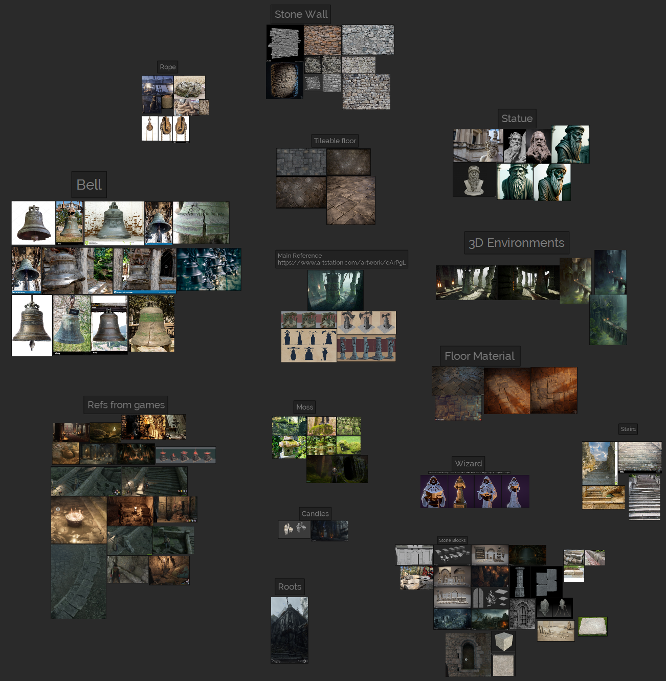
After selecting the concept I would work on, the first step in creating the environment is to collect and analyze references. In my opinion, this is one of the most crucial stages. Every stage in the development of an environment depends directly on the previous one.
For example, if you fail to gather and analyze sufficient references, you will encounter problems in subsequent stages. High-poly models will lack realism, textures will lack detail, and the lighting will be dull and unappealing.
Therefore, I recommend dedicating an appropriate amount of time to each stage of creating a location.
I gathered numerous references for every detail in the environment. Additionally, I discovered a few examples of pre-made 3D scenes and game samples. Collecting references greatly aids in envisioning the approximate appearance of the final scene.
Blockout & Modelling
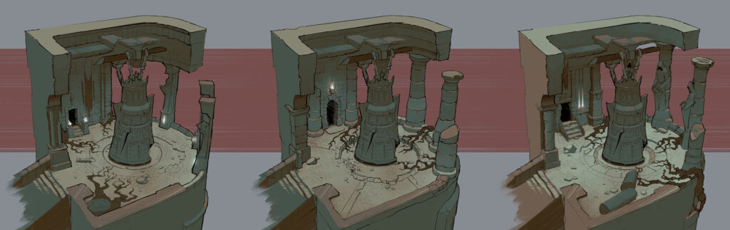
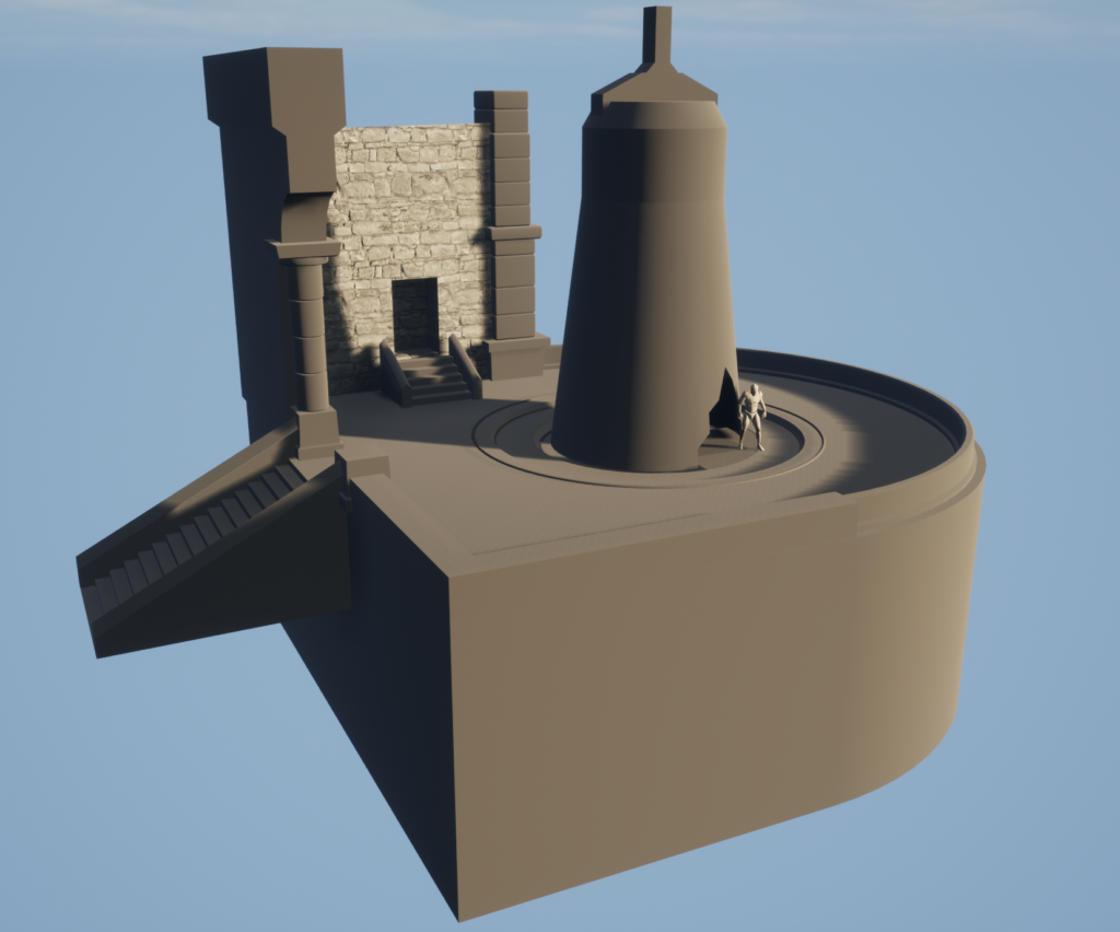
After gathering the references and planning, I start creating the blocking of the scene, beginning with the basic shapes using primitives. Environment blocking is very important as it allows you to present the final look of the scene in as little time as possible.
Moreover, the simple forms used in the blockout enable quick adjustments to the proportions of objects if any mistakes are noticed. At the blockout stage, it is crucial to use a mannequin to ensure realistic object sizes. For example, you can utilize the standard mannequin from Unreal Engine.
By the way, it’s important to keep in mind that when creating game environments, doors, windows, and generally all passages through which the player can enter are often made larger than in the real world. This is done to accommodate the camera and the collisions of the game character. Sometimes, larger doors are also part of the location’s design.
After confirming that my blockout matches the proportions from the concept and has a realistic size, I proceed to import the meshes into the game engine and adjust the basic lighting to gain a better idea of what my scene will look like in the final stages.
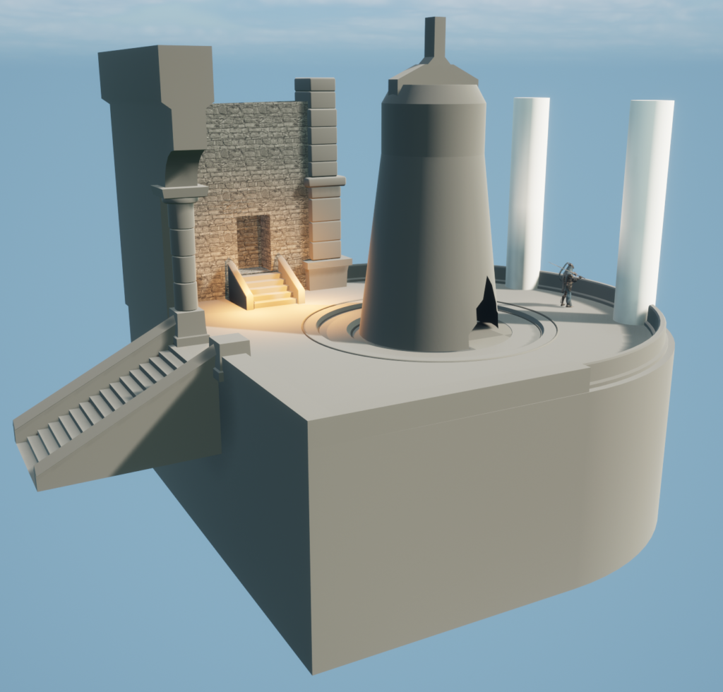
After creating the blocking, I begin to model more details on the objects, refining the shapes to resemble the final result.
This stage enables me to gain a better understanding of the required textures.
Where tile textures will be needed, where trim textures will be needed, and where unique textures will be needed.
Furthermore, with more detailed modeling, the scene starts to resemble the final results closely, albeit without the inclusion of small details and textures.
By this stage, nearly all the objects are already positioned, and the proportions should appear satisfactory. Only minimal adjustments to the proportions will be permitted going forward.
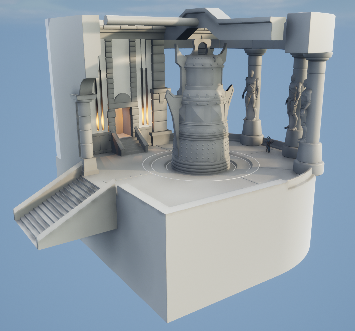
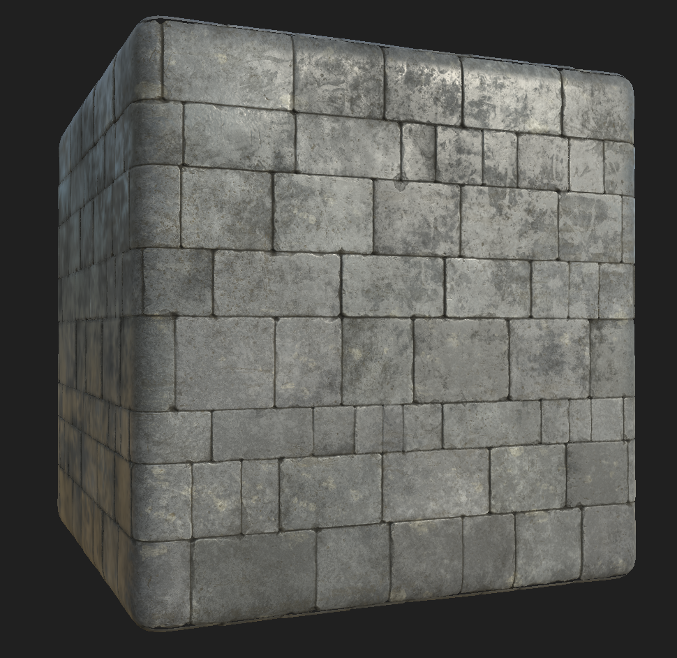
And also, after more detailed modeling, I like to apply basic tile materials from Megascans to objects where they will be needed. This allows me to estimate what tile materials I will need to create in the future.
For example, in the picture below, you can see that I have applied tileable materials to the floor and walls. These materials were sourced from Megascans, and they will be later modified or rebuilt from scratch.
High-Poly & Sculpting
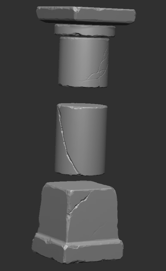
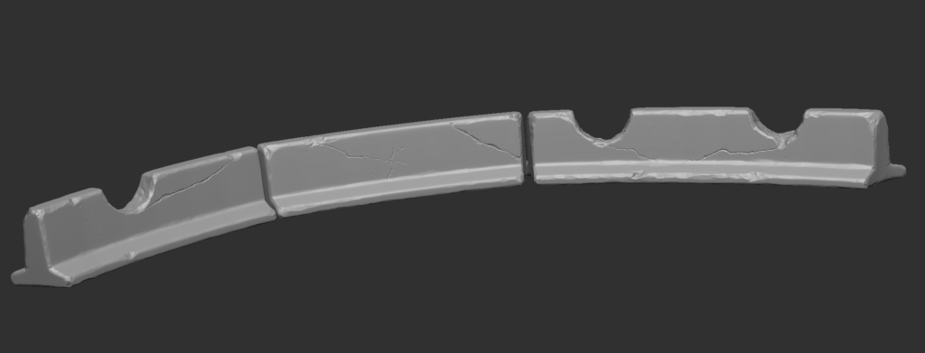
Creating high-poly assets was one of the most time-consuming processes. Since I decided to use unique normal maps and masks, almost all of the assets had to be hand-sculpted. I started by sculpting the stone objects, such as the stones on top of the scene, square columns, etc.
When creating stone objects, the most important thing is to pay close attention to sculpting the damage on the edges. For this purpose, I often used the “TrimSmoothBorder” brush with a square alpha, as it is very effective at creating damage on rocks.
Additionally, in some cases, I had to use brushes like “Trim Dynamic,” “Clay Buildup,” and “DamStandard” for cracks. While sculpting the first stones, I added details on flat surfaces using different stone alphas. However, later on, I decided not to include these details and focused only on the damage on the edges, as the detail on the flat surfaces would be added from a tileable texture.
Below, I have attached pictures of the stone sculpts I created for this scene. Here are some tips that helped me speed up my sculpting work:
1) Start sculpting from large details and gradually move to smaller ones.
2) You don’t have to sculpt every mesh uniquely. For example, if the object consists of 10 identical objects, it is enough to sculpt only 3-4 stones, then copy them and rotate them so that the repetition of details will not be noticeable.
3) Do not get stuck too long on small details. Sometimes, you get carried away with the process and sculpt a corner of the stone for a very long time, trying to create numerous small details. You shouldn’t do that because, due to the small Texel Density, the small details will be lost after baking the Normal Map. The main thing is to make the basic shapes of rocks and damaged parts look good from a distance, from the player’s eye.
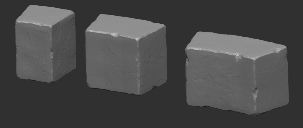
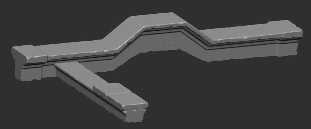
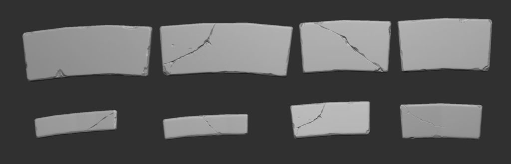
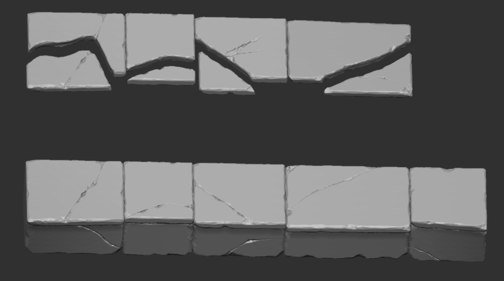
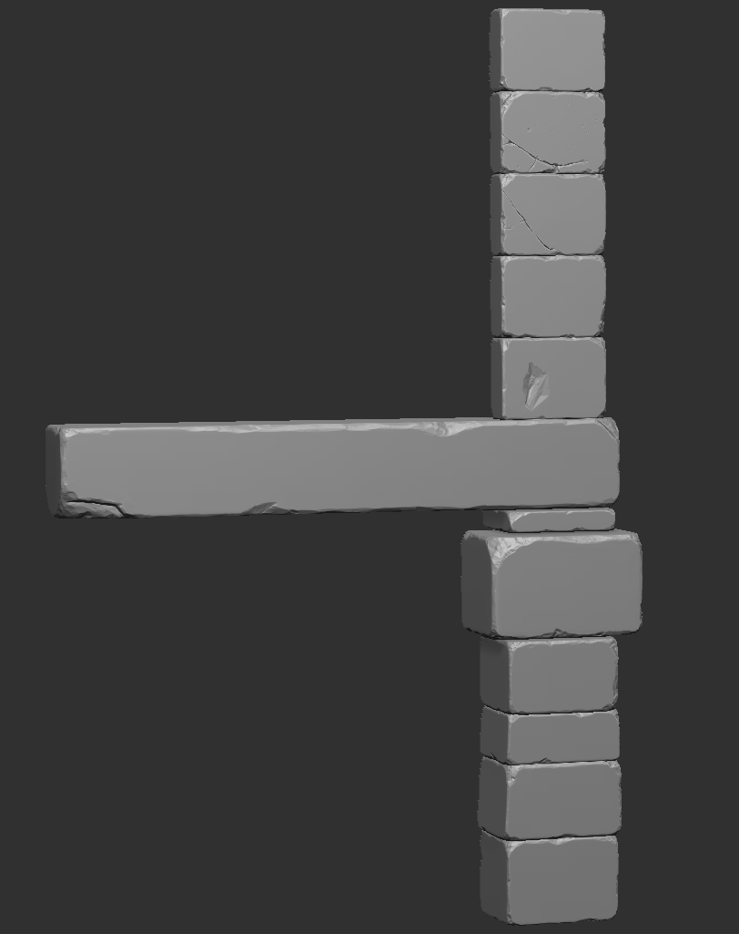
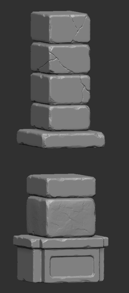
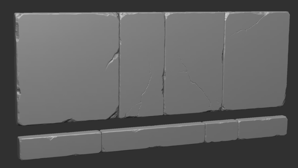
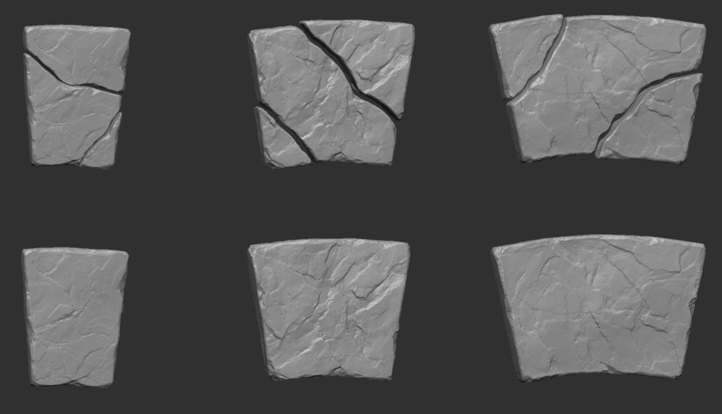
As you can see, most of the high-poly meshes are created using the same workflow. I’ve been sculpting the damage on the edges, sometimes adding cracks using brushes with crack alphas.
I highly recommend the Marble Damage brushes from Paul Tosca; they are great for creating cracks and details on stones.
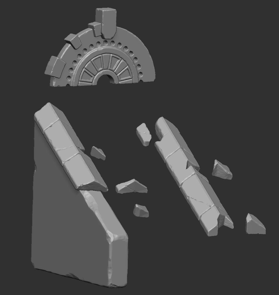
But for some stones, I also created variations so that stones could be used both unbroken and destroyed. For example, I did this for the stairs and the big stones in the center of the room. This way, shapes become more interesting. You can also scatter the broken pieces around different areas of the scene for extra details.
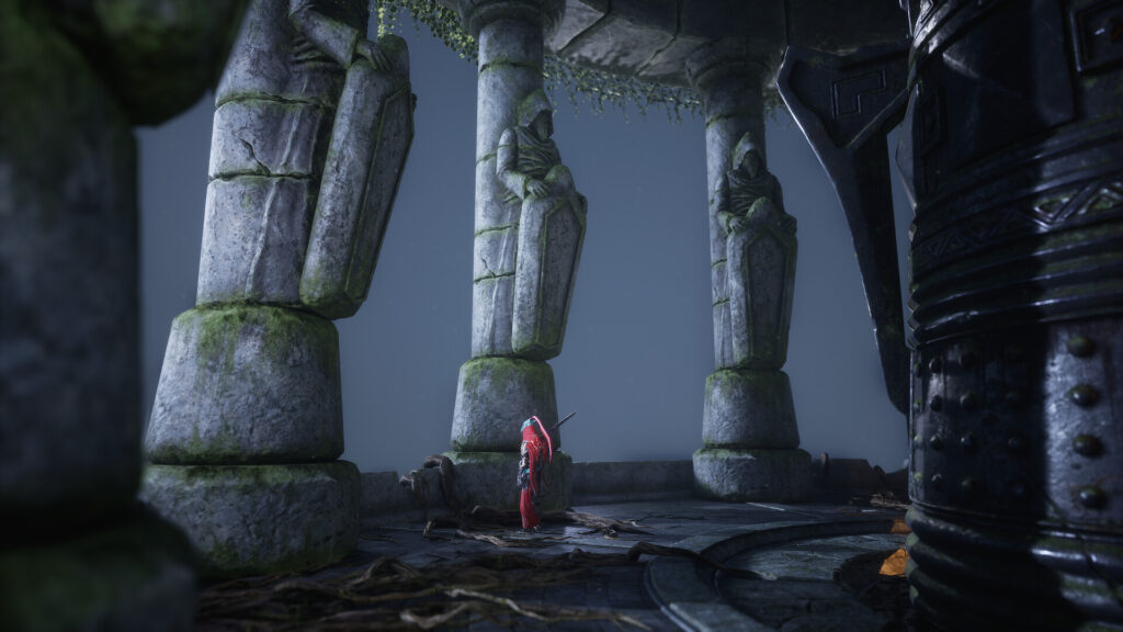
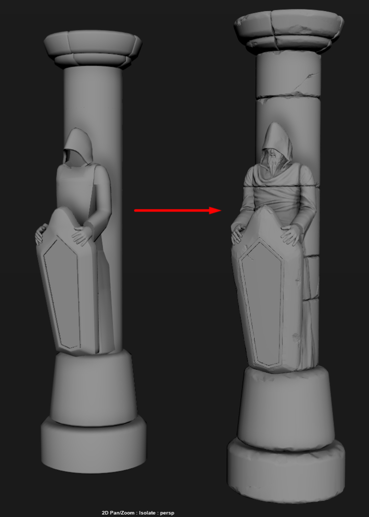
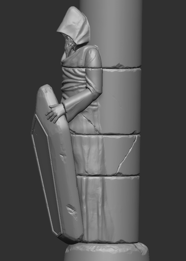
One of the difficult objects in creating high-poly was the columns with the statues. I don’t have much experience in character sculpting, and initially, it seemed that I would need knowledge of anatomy to make the statues look realistic.
But since most of the body of these statues is covered by clothing, it was enough for me to create basic models in Maya and then export them to ZBrush to finish sculpting the details of the stone statues and the damage. This is what the base model and the final sculpt of the columns look like:
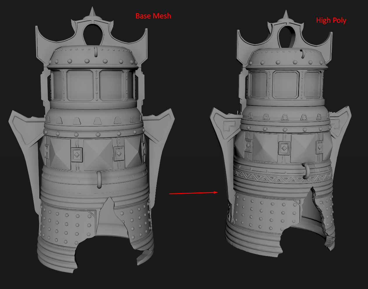
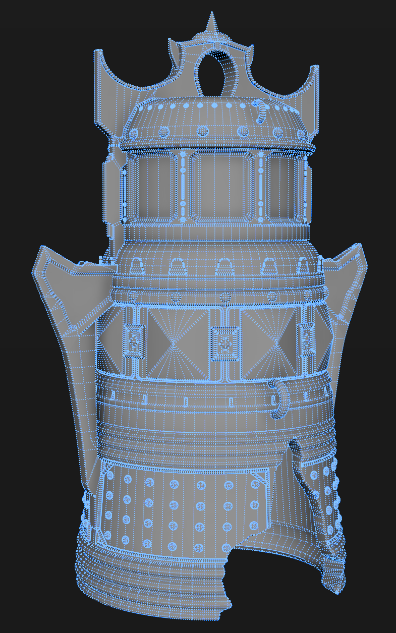
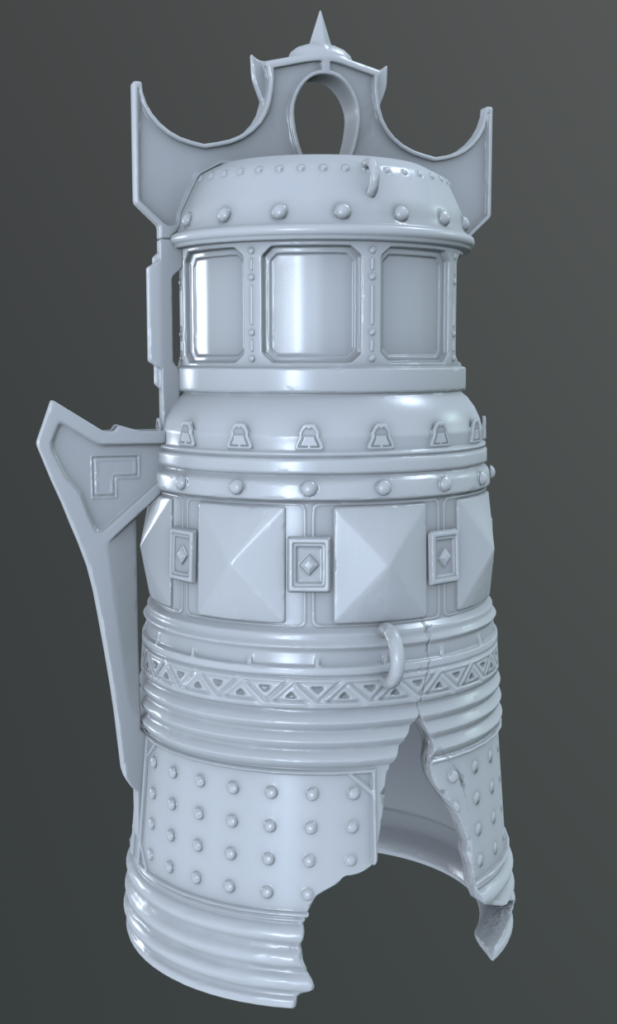
Also, one of the most detailed high-poly objects was the bell. For it, I also used a pipeline with a baked unique normal map and unique masks. However, instead of the stone tileable material, I used a tile material of metal, rust, and moss on the bell.
Firstly, I modeled the basic shape of the bell and small details in Maya and then exported everything to Zbrush. I sculpted the damage and drew the pattern with the “DamStandard” brush. The hole in the bell was created using the Boolean function in Zbrush.
This is a very powerful tool that allows you to subtract or merge geometry without paying attention to topology. Additionally, Boolean in Zbrush allows you to see results in real-time and move or edit meshes until you achieve a satisfying result.
Roots – High Poly
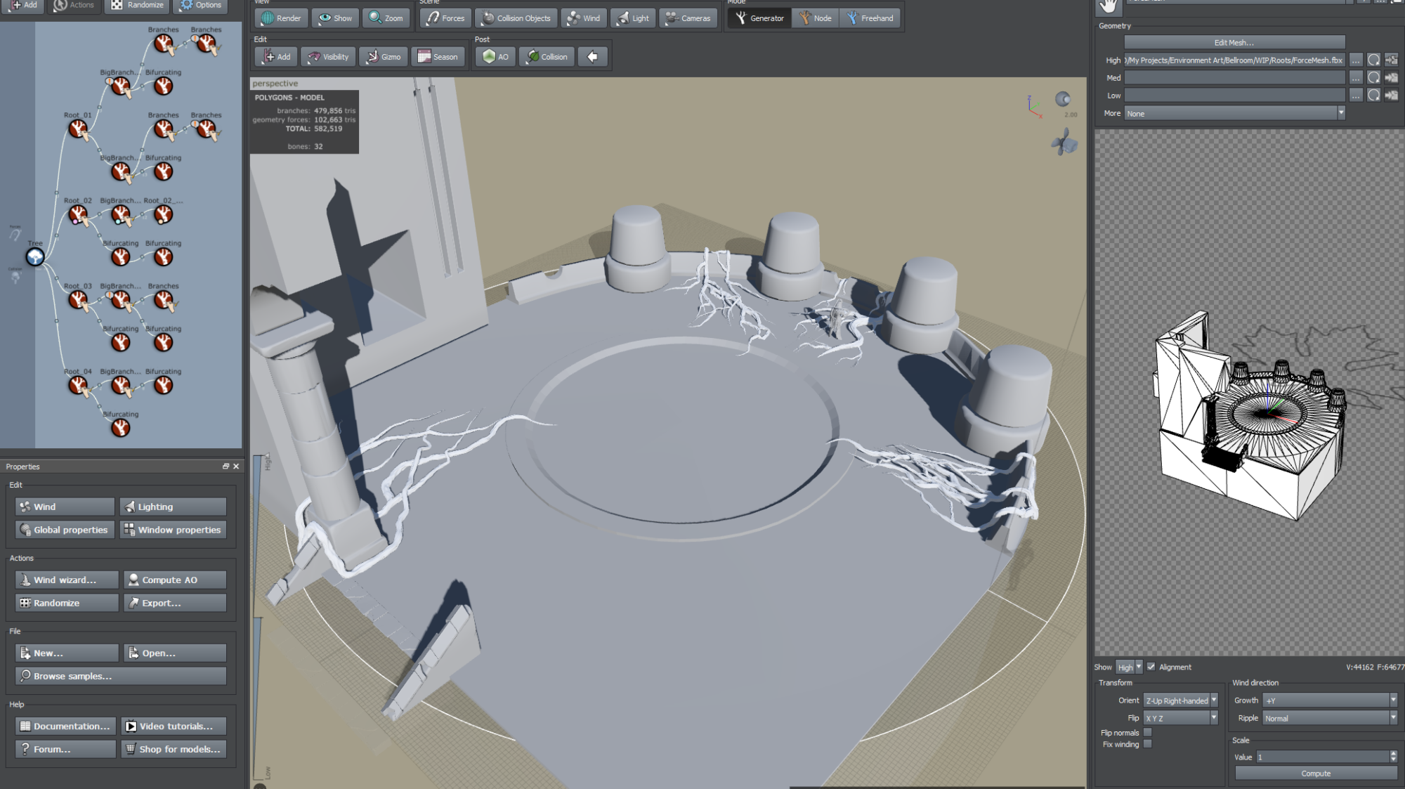
I used SpeedTree to create the roots. Firstly, I exported the main objects of the scene into SpeedTree to better understand where the roots should be located.
Then, I started to manually create each root using the “FreeHand” tool called “HandDraw”. This is how the scene in SpeedTree looks after creating all the roots.
I will explain how I created them using the example of one root. For all the other roots, the process was exactly the same, except that I drew slightly different shapes of roots and sometimes added additional branches.
- Firstly, add a hand-drawn trunk to a tree node.
- Hold down the space bar and click anywhere on the ground as long as it fits into the radius of the tree; otherwise, the trunk won’t be created.
- You can increase the radius of the tree to see it better. Then, while in “Hand Draw” mode and holding the space bar, you can draw the shape of the root. This way, you can quickly get the shape you want.
- Then, you can add a Hand-Drawn Trunk to the previous tree trunk in the same way and finish drawing branches of the desired shape.
Also, standard “Bifurcating Branches” from SpeedTree work very well for the roots.
- When you have created the shape of roots and branches, you can also tweak some parameters a little bit: add more polygons in the “Segments” section, add Displacement using Noise to make roots look more interesting.
LowPoly
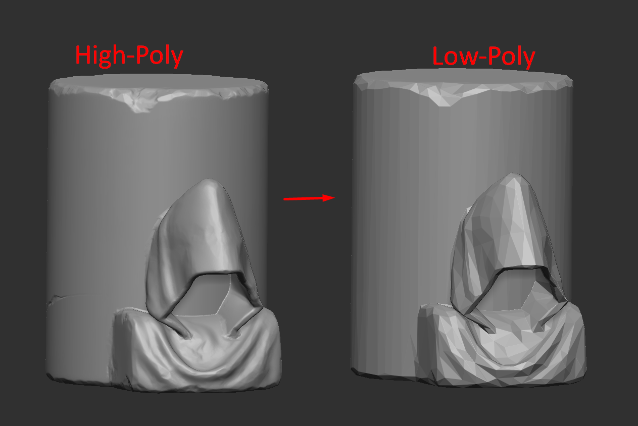
Creating low-poly meshes for this scene was not a difficult task. Since I used Nanite in this project, I didn’t have to save too many polygons. For low-poly, I used the “Decimation Master” plugin in ZBrush.
It allows you to reduce the number of polygons, removes unnecessary polygons on flat surfaces, and leaves geometry only where there are large details on high-poly. Also, the advantage of using the Decimation Master is that on low-poly, you get an interesting silhouette, which is difficult to achieve using hand modeling.
Decimation Master is great for creating low-poly meshes for organic objects such as rocks, cliffs, statues, etc., but is poorly suited for cases where a clear wireframe is needed on low-poly.
Here’s an example of how Decimation Master turns a high-poly model with approximately 500k+ triangles into a low-poly with only approximately 800 triangles.
I used Decimation Master for almost all meshes, but for the bell, I wanted to achieve clear topology. Therefore, I created a backup of the base mesh before exporting it to Zbrush. It is highly useful to maintain backup copies of meshes as they prove handy at different stages of development.
Next, I optimized the wireframe of the base mesh by removing excess polygons, adding more polygons to enhance the smoothness of rounding. Additionally, I utilized Boolean to create a hole on the Low-Poly model.
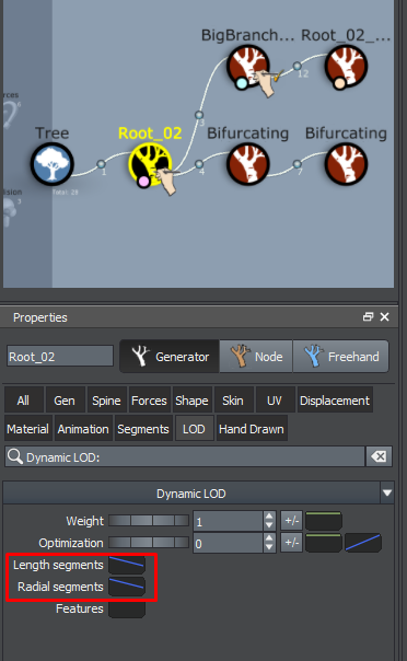
Roots Low-Poly. To create low-poly geometry for roots, I used the LODs system in SpeedTree. The most important thing when creating High-Poly roots is to use a number of sections on the cylinders that is a multiple of 4.
This way you will get clean wireframe on Low-Poly, which is easy to work with and for which it’s easier to make UVs. And so, to create Low-Poly geometry in SpeedTree, just edit the curves “Length Segments” and “Radial Segments” in the LOD section.
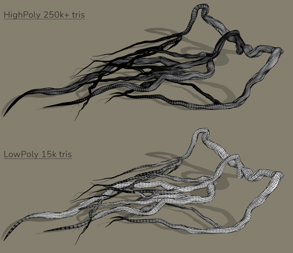
Of course, for Low-Poly you could achieve a less dense mesh and save some more polygons, but because I used Nanite and it was a personal project, even a few thousand extra polygons won’t hurt.
But in terms of development, it is, of course, better to try to optimize the geometry as much as possible, and SpeedTree is also good at this because you can adjust the density of the mesh on each branch individually in the LOD section, using the “Node.” mode.
UVs
After I created the high-poly sculpts, I converted them into low-poly meshes and I moved on to creating the UVs. In order to make the pipeline using unique masks and unique normal maps + tile materials work, I needed to create 2 UV channels.
The first UV channel was used for tileable materials like stone, metal, floor tiles, etc. For this stage, the main thing was not to create unnecessary seams and keep a good TD (~8-10 px/cm). The second UV channel was used for baking a unique Normal Map with the high-poly on it, as well as for texturing masks to be used for adding dirt, moss, rust, and variation in color on the tiled material from the 1st UV channel.
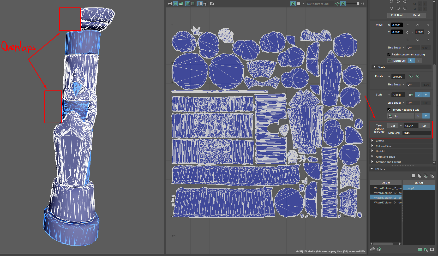
Let me show you how I created the UVs using the example of the column with the statue. First, create unique UVs for the masks. The main thing is to make sure that all the shells fit into the same UV square, and you can also use overlaps to save more UV space.
Since Substance Painter doesn’t allow working with multiple UV channels yet, after I’ve created the unique UV channel, I proceed to baking and texturing, which I’ll talk more about in the next topics.
I create the UV channel for the tile textures only after I make sure that my unique UVs look right and everything is baked and textured perfectly. Creating the UV channel for the tileable textures is pretty easy. I duplicate the unique UV channel and increase the size of the shells to the Texel Density I want.
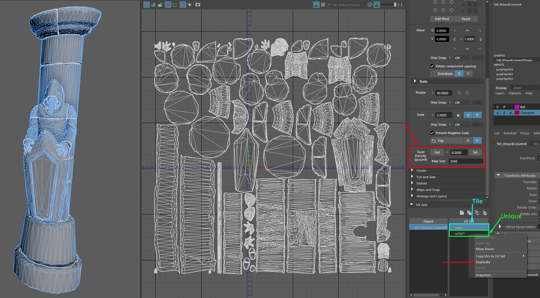
After this, the UVs are completely finished. The unique UV channel remains unchanged, and the tileable UV channel can be changed at any time if needed.
Baking
I use Marmoset Toolbag 4 for baking. Baking texture maps using this pipeline is almost no different from baking when creating props.
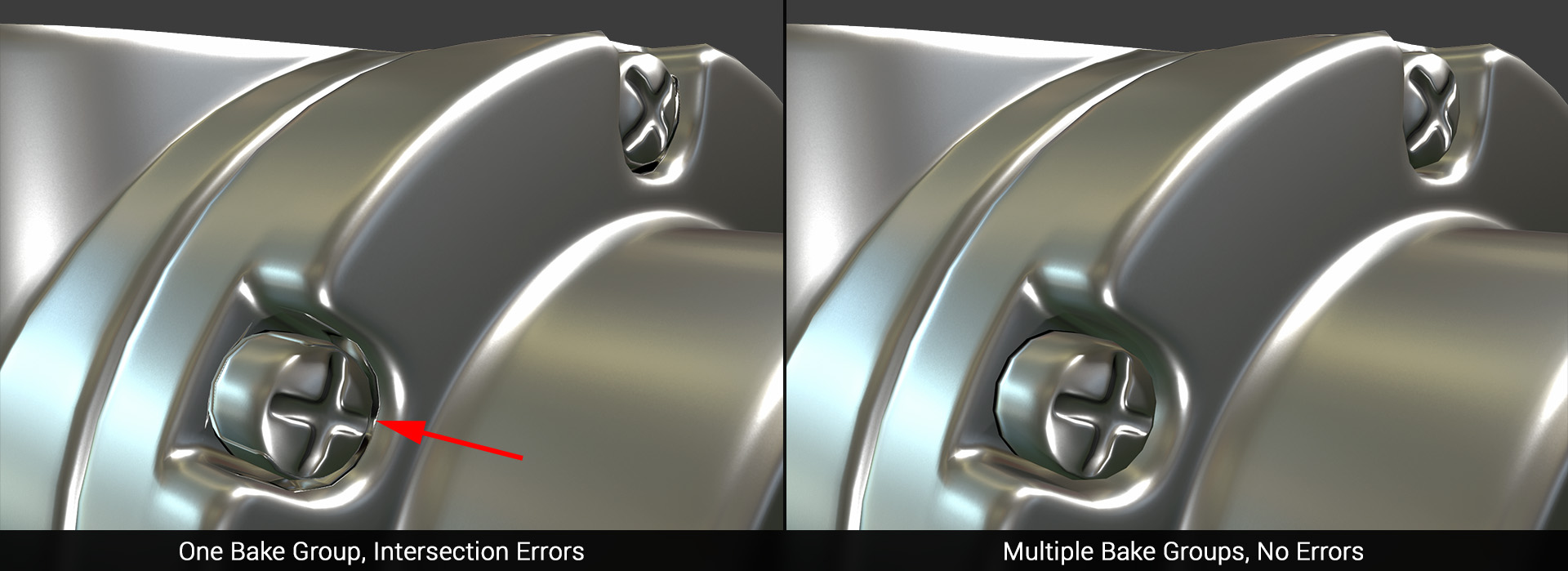
I simply divide the objects using Naming Groups so that the Normal Map of close meshes is not baked on top of each other, and there are no normal overlaps.
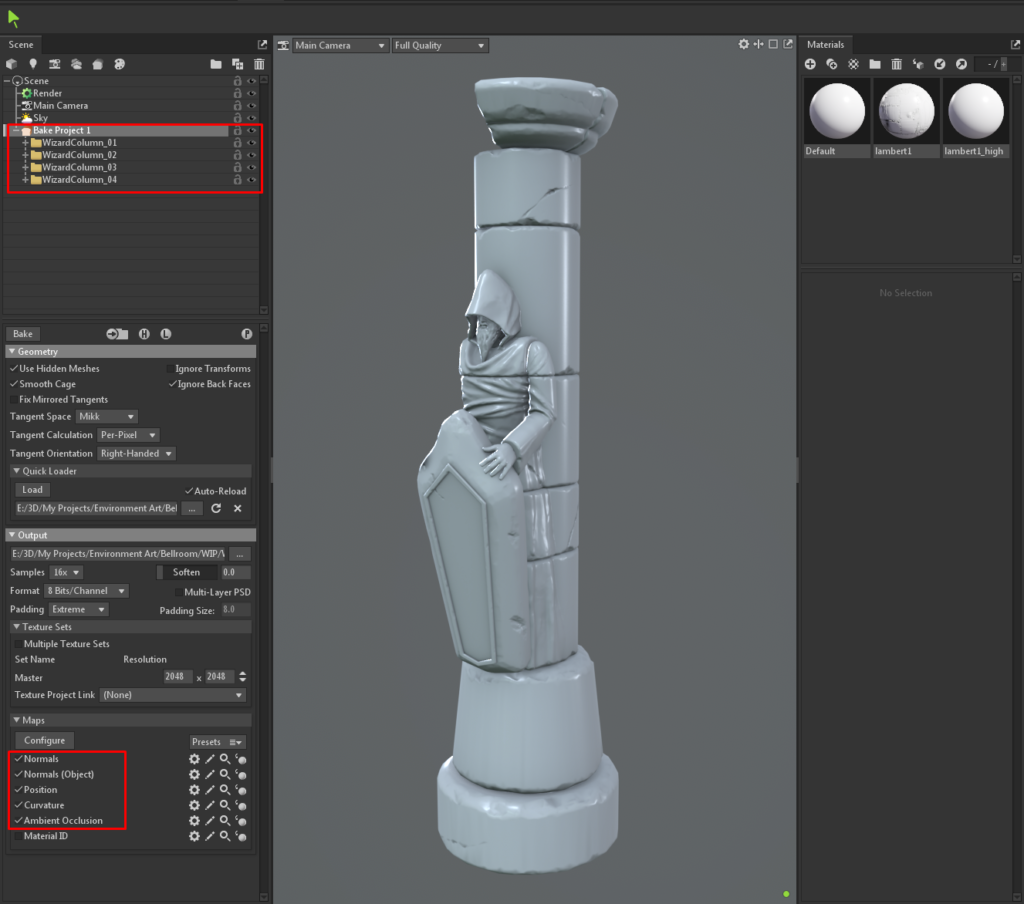
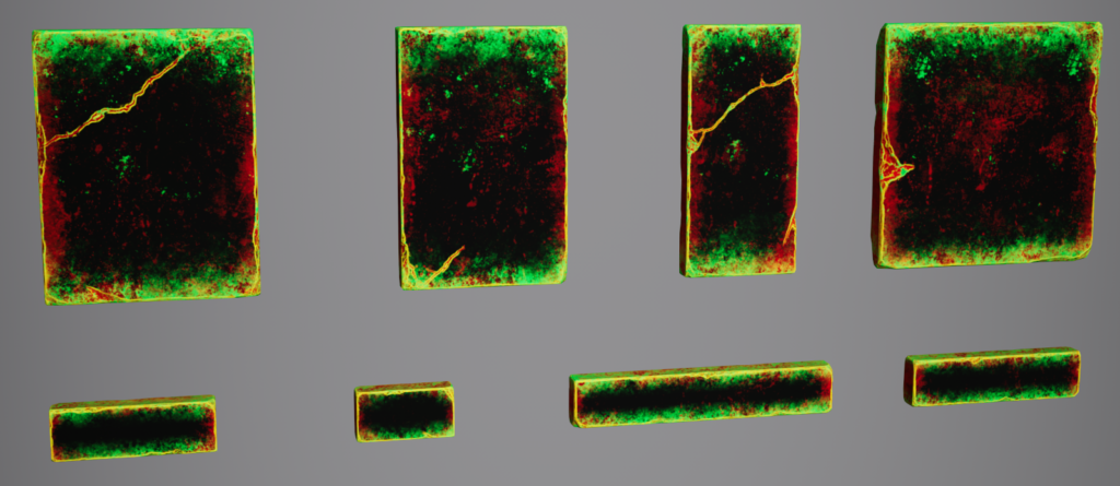
Usually, I bake all the maps I need for texturing masks: Normal, Normal Object, Position, Curvature and AO. Also, sometimes I bake Thickness; it can create quite interesting masks in special cases. Here are examples of what Low Poly looks like after baking.
As you can see, if we have a small Texel Density at unique UVs of ~1-1.5 px/cm, all details from High Poly are still perfectly baked and visible.
Masks Texturing
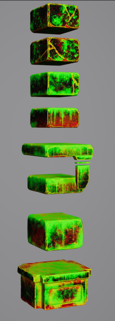
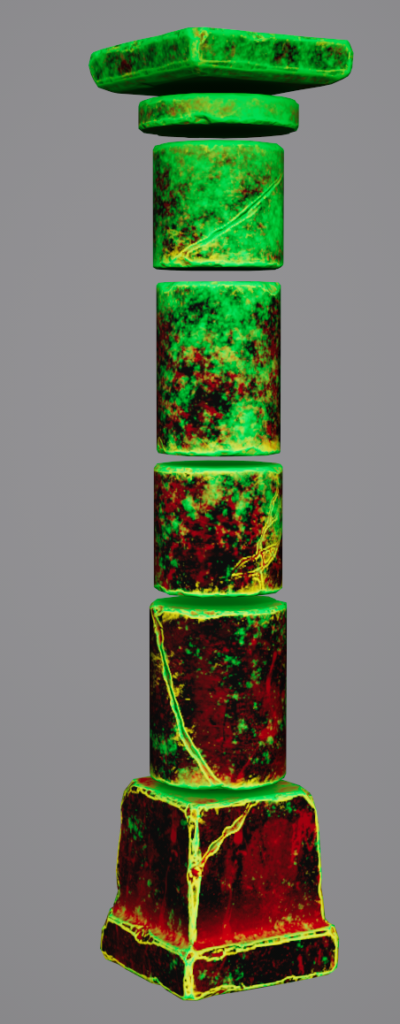
So, when the unique UV channel is ready and texture baking is complete, I proceed to texturing masks. For objects made of stone, I use 3-4 masks:
- Edge mask to brighten the edges.
- Mask for dirt (AO dirt, leaks, ground dirt).
- Moss mask.
- Optional mask for color variation.
The difficulty with using mask texturing is that you don’t immediately see the result of how the model will look in the end with the materials applied. To take a look at it, you should export everything to the engine and check everything there. It takes a certain amount of experience with masks to make them look realistic and visually appealing. Each time, it will get better and better because you will start to understand where masks will look good and where they will look worse.
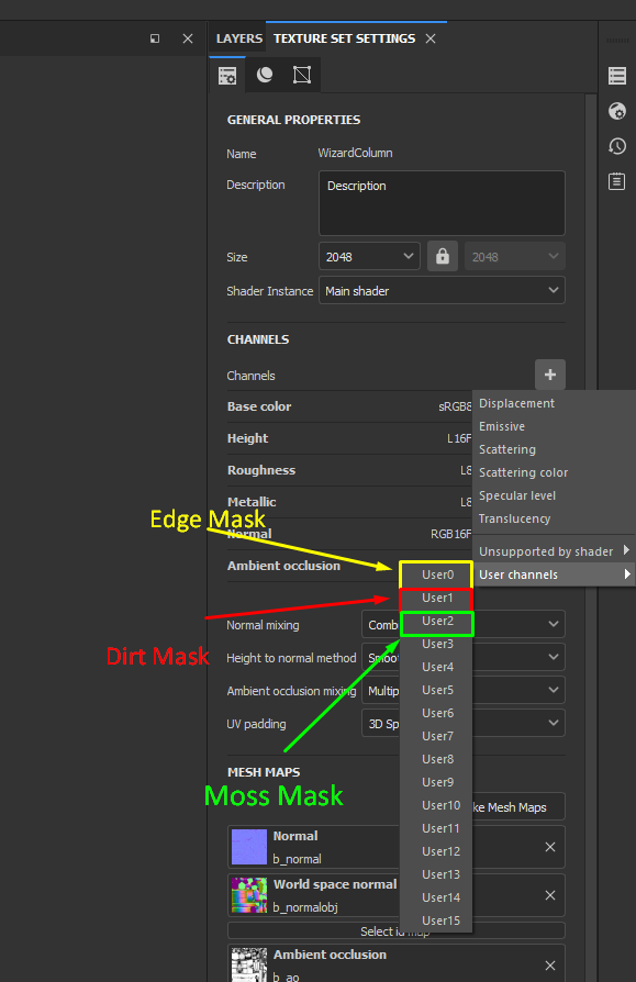
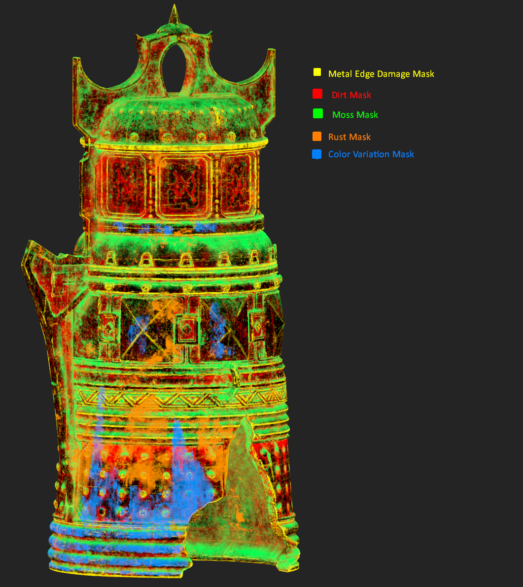
To start texturing masks in Substance Painter, in “Texture Settings,” you need to add “User Channels.” Each channel will be responsible for a different mask. For example, I have User0 – Edge Mask, User1 – Dirt Mask, User2 – Moss Mask and User3 – Color Variation Mask (Optional).
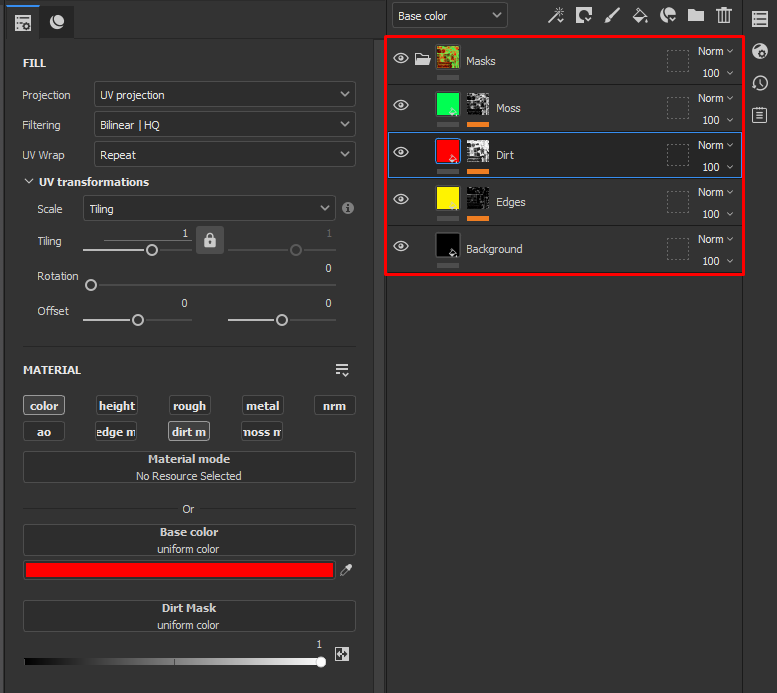
After that, I made a basic smart material to speed up the work with masks. There are only 4 layers in this material: 3 layers for each mask and one background layer to make the masks export as black and white instead of transparent.
If you need it, the material can be downloaded from this link.
I have used this smart material for almost all objects, adding layers and editing layer masks for more logical texturing. Here are a few tips I can give you for texturing masks:
- Pre-made masks from Substance Painter are best not used in their pure form. They’re good as a base for masks, but it’s better to spend some time tweaking and varying them.
- As often as possible, use stencils and alphas made from real photos and references. They greatly add realism to the textures, as well as save a lot of time.
- Analyze the references, study where there is dirt on the objects, where moss grows from, how rust appears, etc. This greatly enhances your texturing skills.

For the bell, I used slightly different masks since the bell is made of metal. I needed rust masks and color variations for it. This is what the final bell masks look like:
Tileable Materials
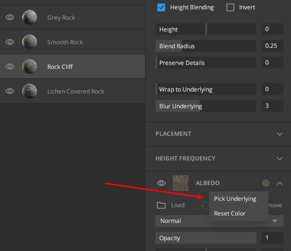
I used Quixel Mixer to create most of the tileable materials. It allows you to quickly obtain beautiful tile materials by utilizing scanned data from Megascans. It’s a simple software with not much to explain about its usage: we simply search for the most suitable materials from Megascans, add them to the project, and adjust the layers to achieve a visually pleasing result.
In Quixel Mixer, there is one function that many people might not be aware of: by clicking on the color of a layer, you can utilize the “Pick Underlying” function. This feature is excellent for selecting colors from the layers below, enabling you to combine colors and make different materials appear more similar to each other.
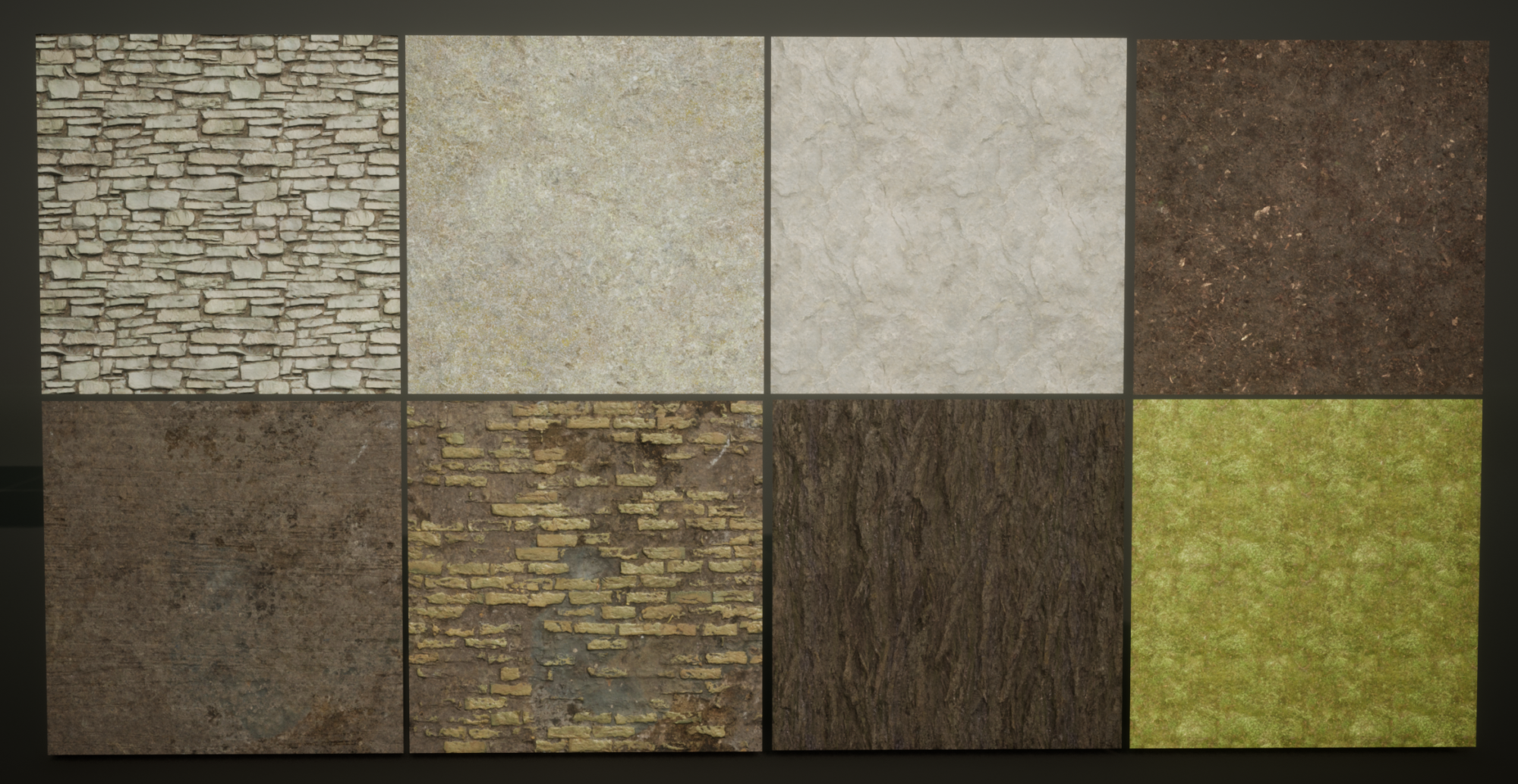
Here are the materials I made in Quixel Mixer:
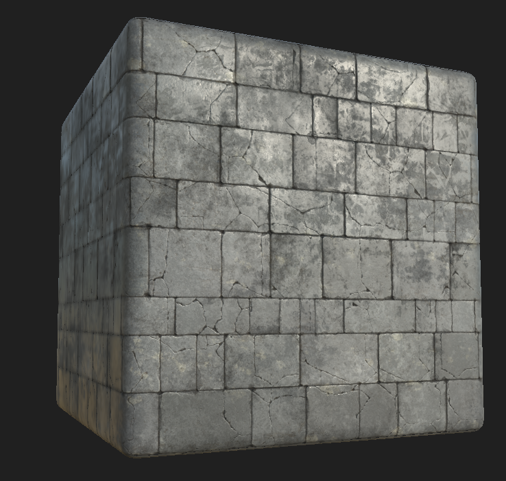
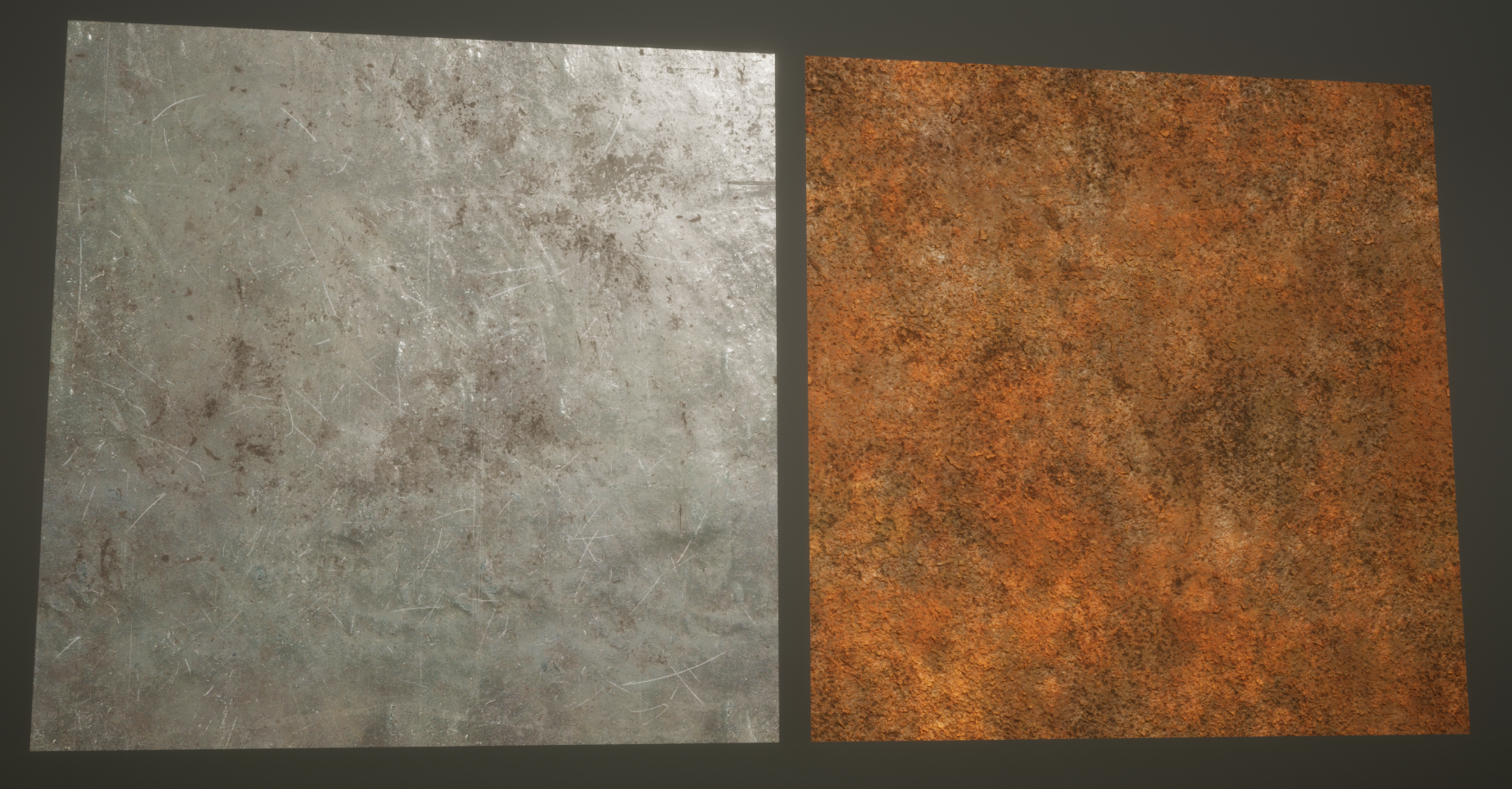
But some tileable textures I made by hand in Substance Designer and Substance Painter, like the tile materials on the floor, rust, and metal material.
For example, here is the tile material made in Substance Designer that I used on the floor. It’s a pretty simple material in general, but even it does a great job. I also made a variation of this material with cracks. In the final scene, I blended these two variations using masks for a more interesting result.

And also, here are the metal and rust materials that I made in Substance Painter. There’s also nothing complicated here. As for the LowPoly, I used a regular plane, the UVs of which take up a whole UV square.
Then, by simply adding layers and following the references, you can create a good tileable material.
Ropes
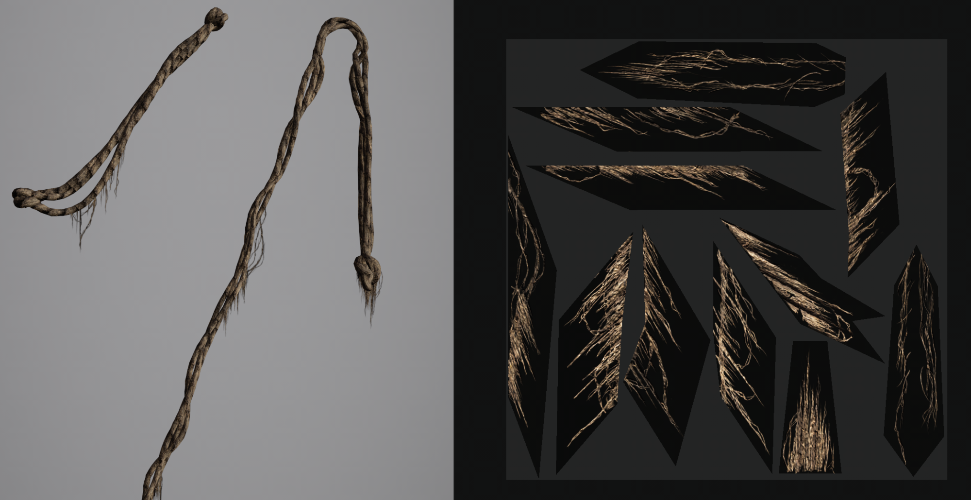
To create the basic shapes of ropes, I used the “CV Curve Tool” in Maya. I created three curved lines woven together, and from these, I already obtained the rope geometry using the QuickPipe plugin.
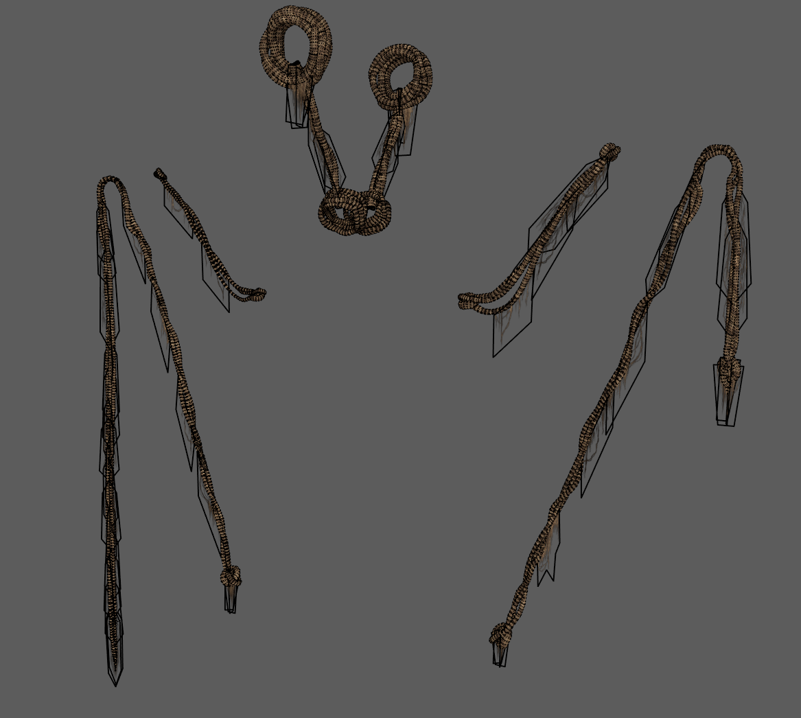
And to create the rope scraps, I made an atlas of transparent textures. Firstly, I just created planes in Maya in the areas where the pieces of rope seemed the most logical, created UVs for these planes, exported them to Substance Painter, and there applied the rope material.
I created masks for transparency. For the masks, I did not use any ready-made stencils; all masks were drawn by hand.
Shaders in Unreal Engine
To achieve a seamless pipeline for material blending, which involves the use of 2 UV channels and masks, it is necessary to create a proper shader in Unreal Engine.
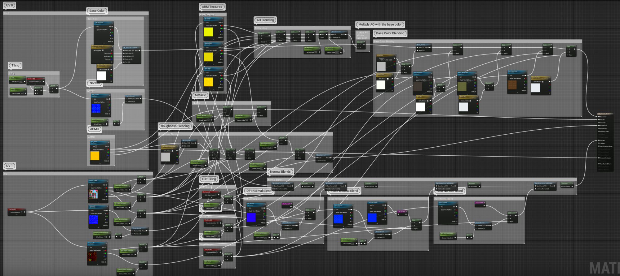
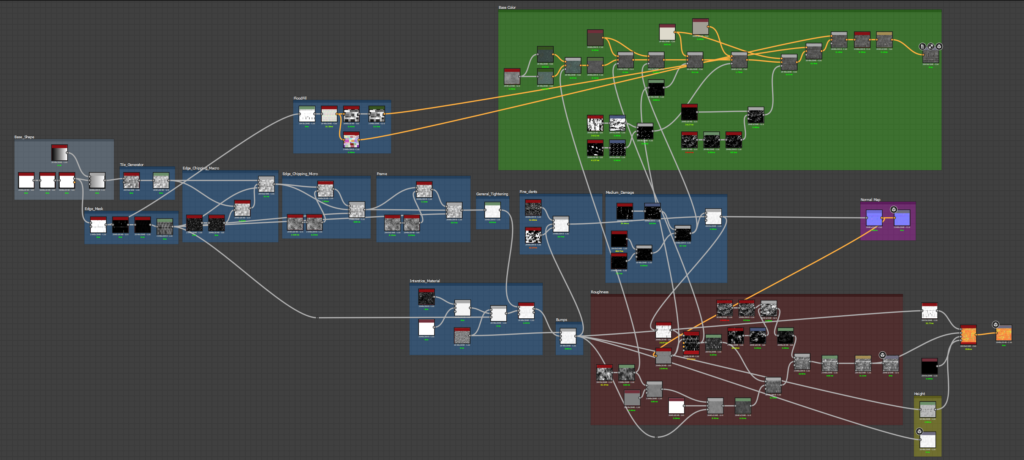
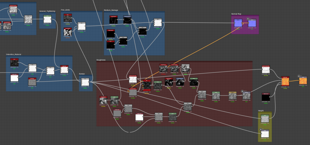
This is what the Master Material looks like, which I used on almost every asset.
Although it seems quite big and complex, in fact, there’s nothing unusual here, and the material is quite light for performance. Here’s the view from Shader Complexity mode.
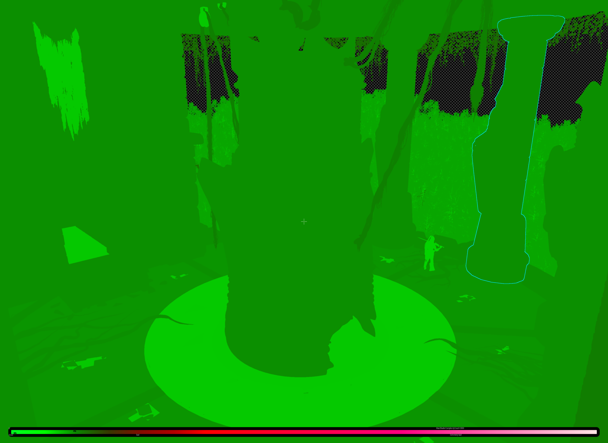
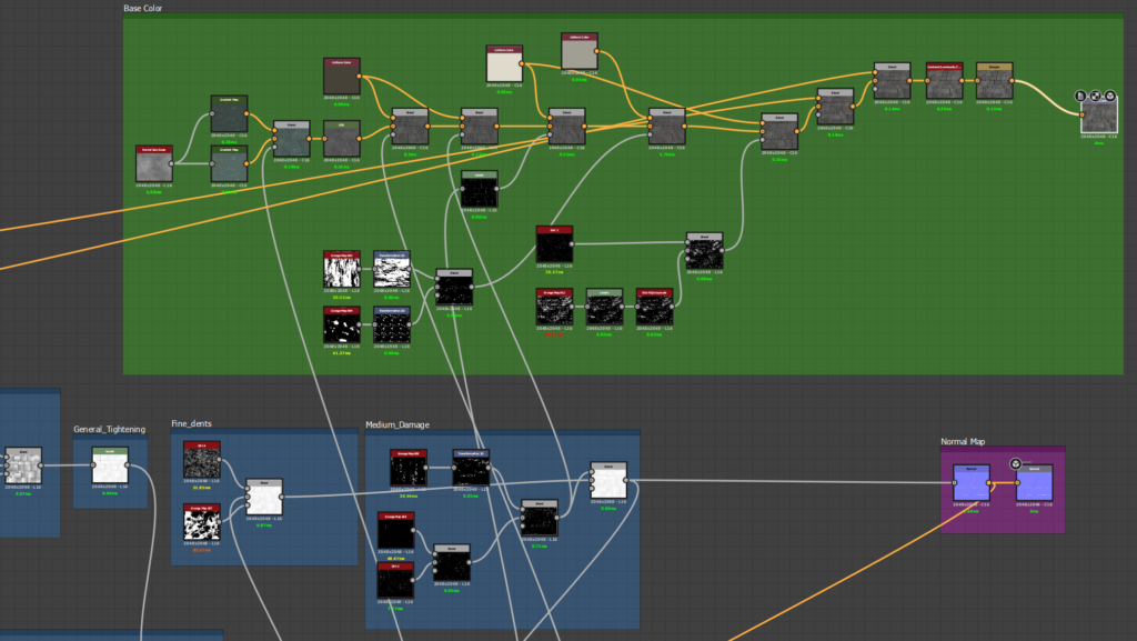
Most of the space on the graph is taken up by the blending of the texture maps for each material. Additionally, for dirt, I use a separate material instead of just a dark color with white roughness. Apart from blending in this shader, I have also incorporated a significant number of different parameters to control the final result.
These parameters include the intensity of the masks, the intensity of each normal map, and the parameters responsible for editing the base color, such as saturation, contrast, tint, etc.
To learn how to work with shaders in Unreal Engine, I highly recommend the following YouTube channels. They helped me quickly grasp the process of creating shaders for environments.
And in addition to shaders, there are a lot of useful Game Dev videos on these channels:
The DiNusty Empire
Ben Cloward
Tiedie
And here are a few rules that allow you to create and work with shaders as efficiently as possible:
- When working with Master Materials, follow the structure of the graph and add comments and frames to make it easier to navigate the graph.
- Parameters should also be structured correctly so that working with instances was more convenient and you don’t get lost in the parameters.
- Experiment and try different nodes, it will allow you to quickly learn about all the features of the editor material.
Lighting
Lighting the scene was one of the hardest parts for me. Because I don’t have a lot of experience with lighting environments, and in this scene, the lighting wasn’t the easiest: a lot of complex fog and no concept for night lighting.
That’s why I had to experiment and in fact, I’m not 100% happy with the final result. But I think with experience I will get better and better results in lighting.
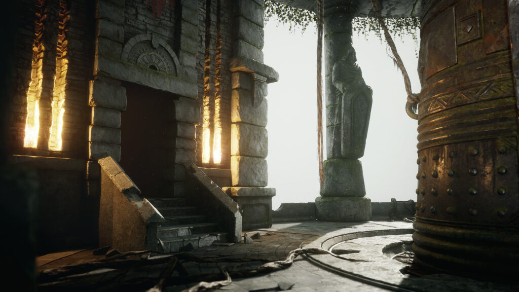
I started lighting by adding Directional Light, Exponential Fog, Sky Light and Sky Atmosphere to the scene, but even if you adjust them perfectly, only having these basic subjects, the lighting will look very flat, boring, dark and not realistic.
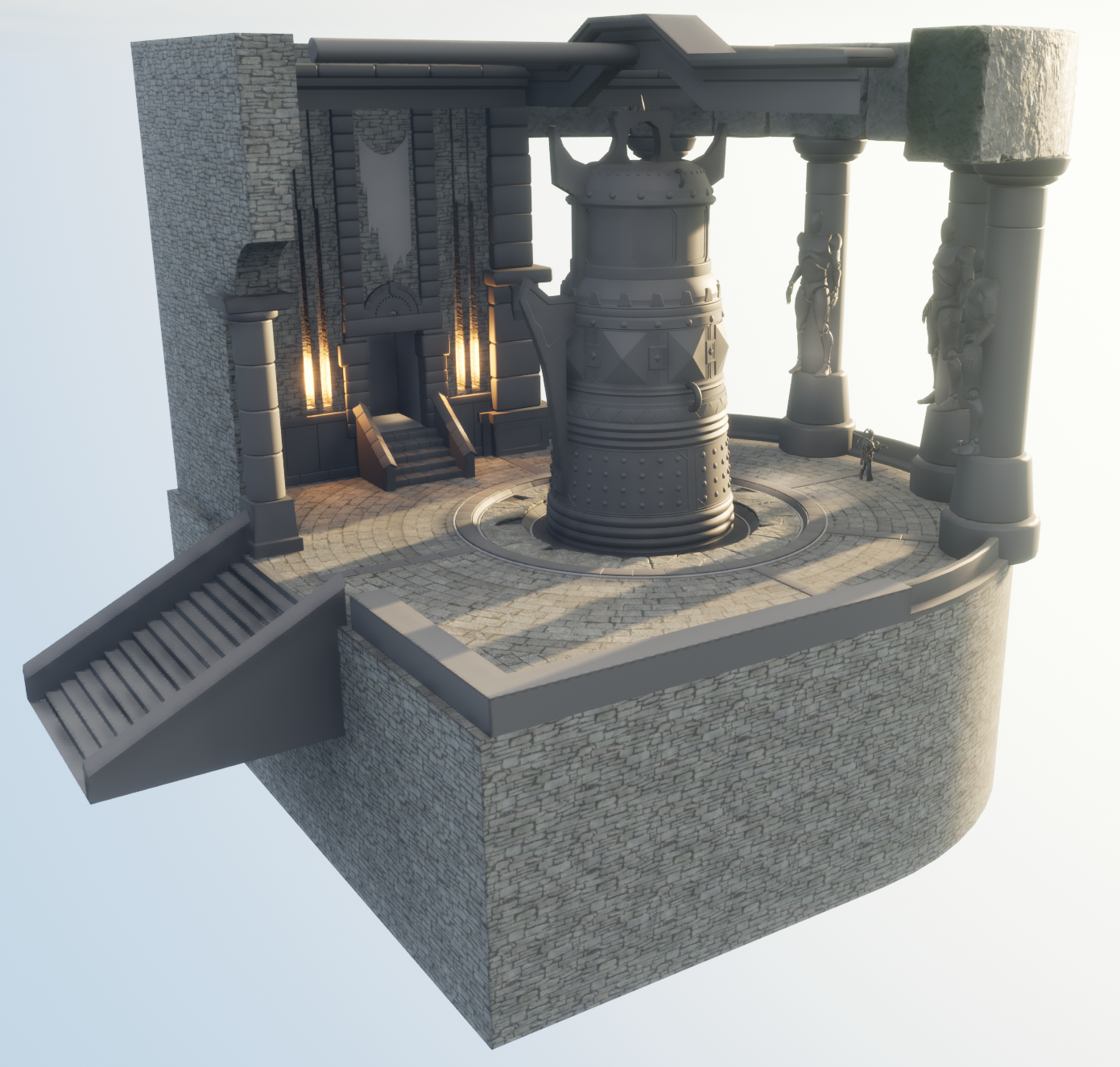
So I began to add fake light sources that will illuminate the silhouettes of objects, highlight very dark areas and add accents on Roughness and this is what the final version of the lighting of the day scene looks like, as you can see the difference from the basic light is huge.
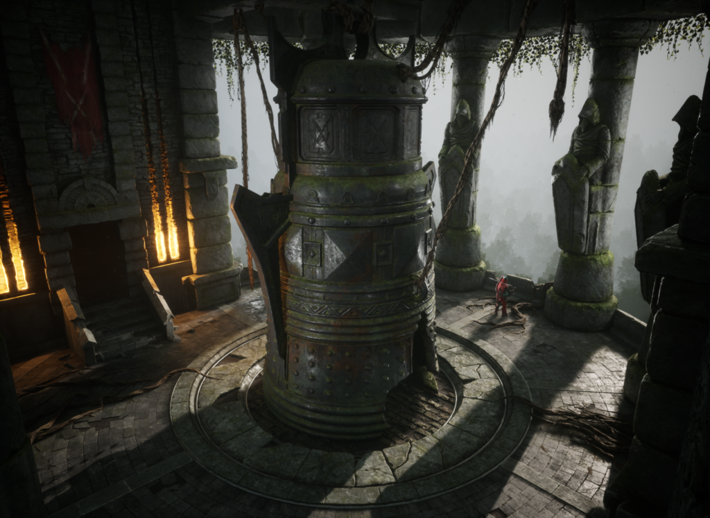
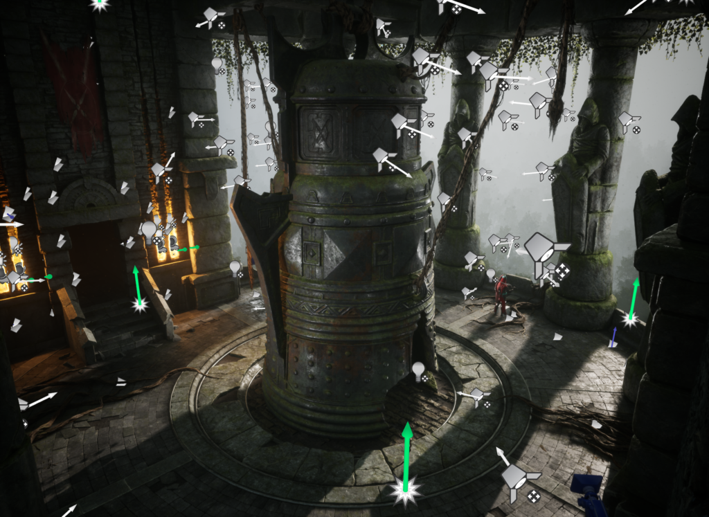
In general, the scene uses 70+ light sources, most of them are Spot Lights as they are much cheaper for performance, but also in some areas used Point Lights for a more beautiful result. I think in the conditions of development, under technical limitations, it is possible to reduce the number of fake sources of light to 15 or even less.
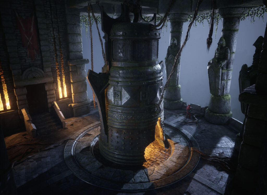
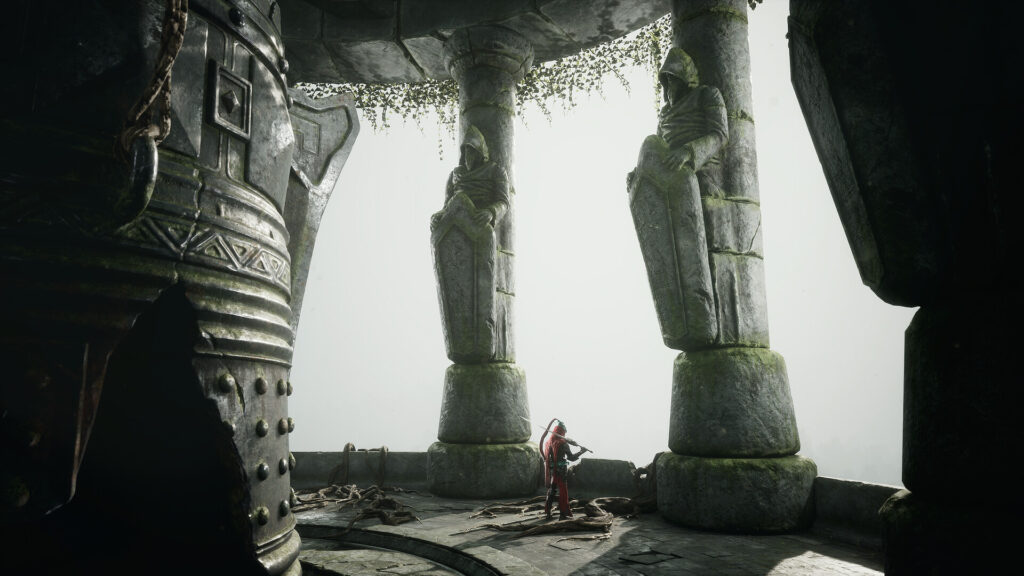
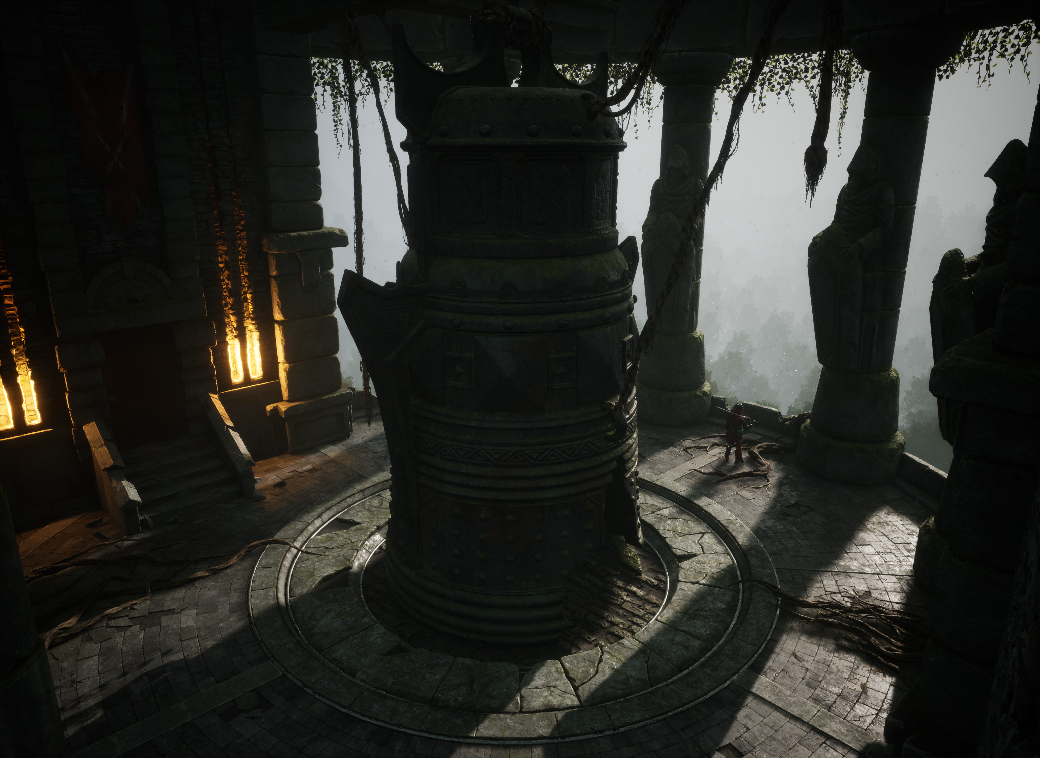
Night Lighting.
To create a night light, I duplicated the level with daylight and began to work with it. Reduced the intensity of Directional Light and Sky Light, increased the intensity of the fog so that the trees in the distance were almost not visible at night.
And also changed the color of Directional Light and the fake light sources imitating the moon to a more blue shade. I also had to change the color of the light scattering in the fog to a darker color for a realistic result.
The most important thing when creating night lighting is not to make the scene completely black so that no details can be seen.
You should avoid completely black shadows, and for artistic purposes, it is better to make the picture brighter than it would be in real life. This way you will get more pleasing to the eye results and the players will not have problems with too dark areas in the environments.
Background & Trees
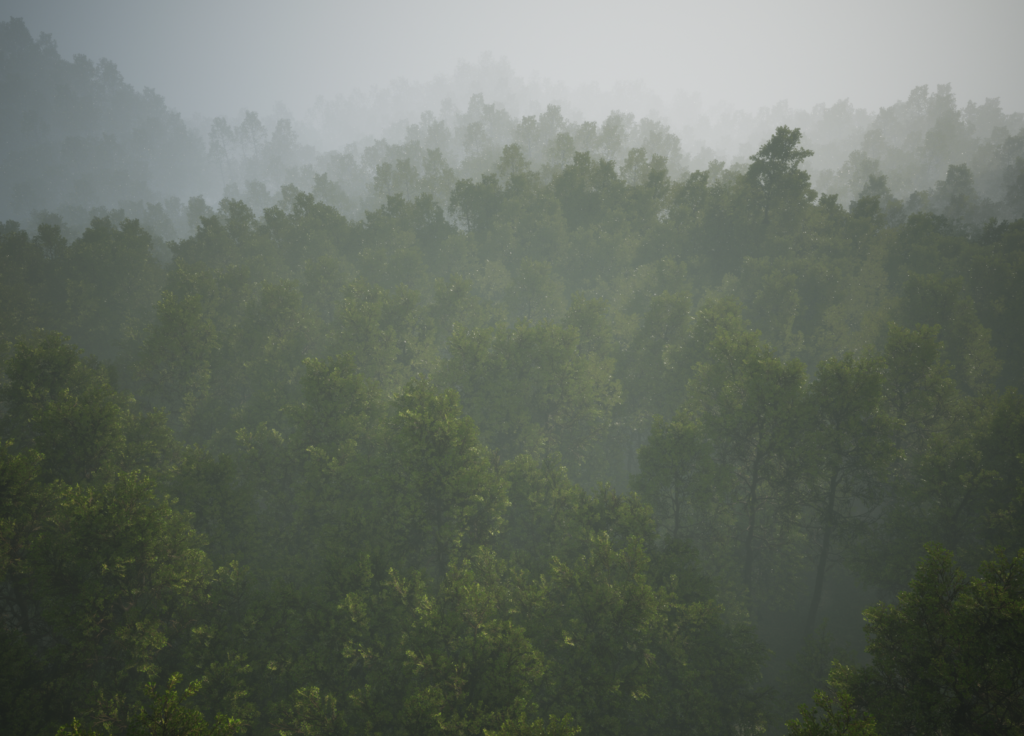
To create the background I made a small Landscape, using the Landmass plugin in Unreal Engine 5. It allows me to quickly get a good basic shape of mountains, and for my task, it was enough, because in the final scene, the Landscape itself is almost not visible and is used mostly as a ground for trees.

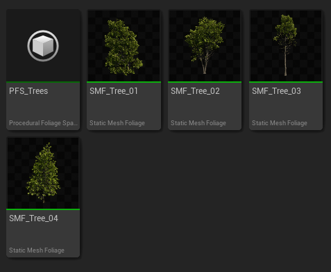
For the trees, I used the pack from Quixel Megascans.
Megascans Trees: European Black Alder (early access).
And arranged them on the Landscape using the Procedural Foliage tool. It makes a very fast automatic arrangement of vegetation, especially good for background vegetation when you do not need to arrange the foliage manually.
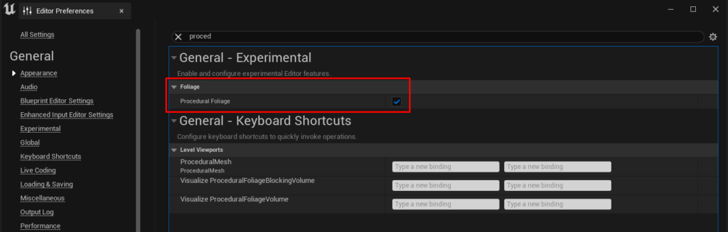
To use Procedural Foliage, you have to check the box in “Editor Preferences.” There are a lot of different tutorials on YouTube on Procedural Foliage, so it will not be very difficult to understand the functions of procedural foliage.
Polishing & Decal pass
After the environment is almost completely ready and good lighting is done, I moved on to the polishing stage, the scattering of decals and small assets around the scene. This stage is quite simple and meditative. I used Megascans decals of leaks, falling leaves, cracks, and debris on the ground.
In general, since I was using a pipeline with masks, I already had the decals and cracks textured so decals were used very little in this scene.
Rendering
For the rendering, I used not only static frames but also recorded a few short video clips to show the environment in more detail. I used Level Sequencer and Movie Render Queue to record the video.
Here are some good tutorials that helped me understand video rendering in Unreal Engine 5:
Post Process
After the project is completely finished and the renders are ready, I like to import everything into Photoshop and work on post-processing and creating a custom LUT for Unreal Engine. I think this a very important step, which will improve the final result much more.
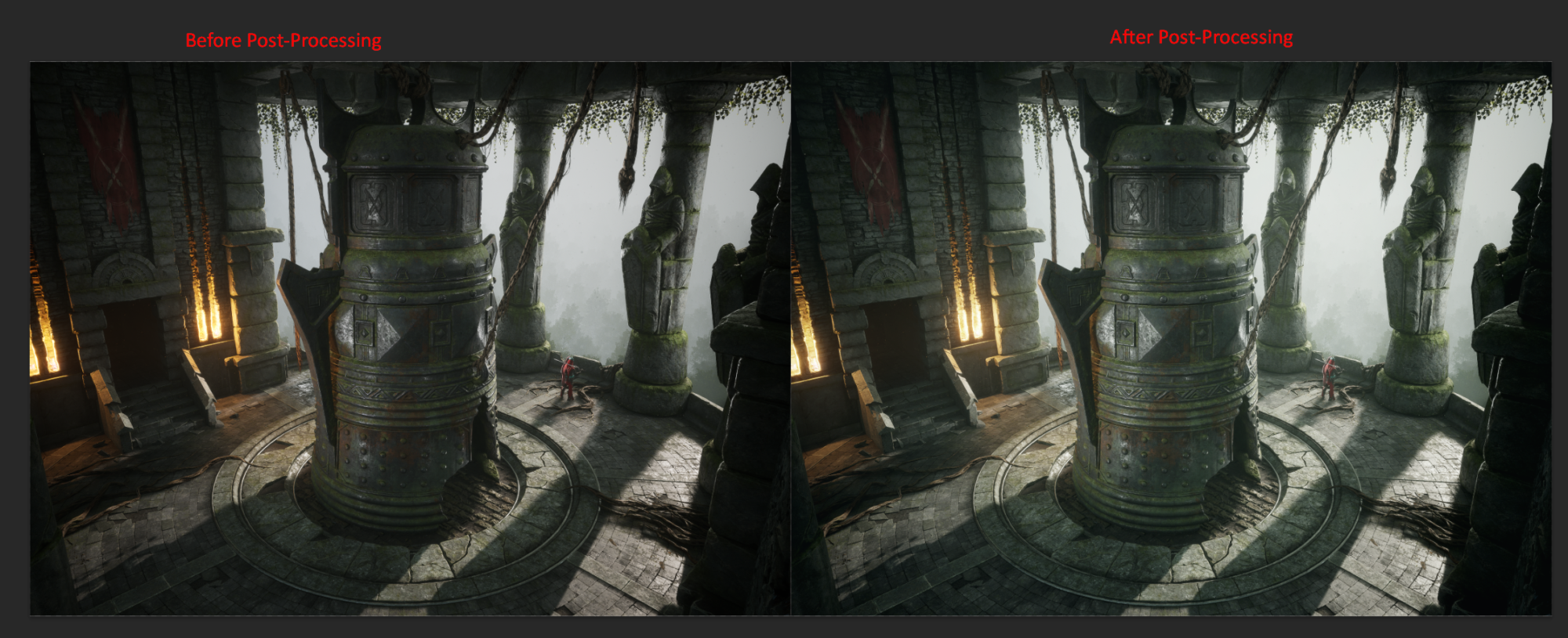
Here’s great documentation on making a custom LUT and using it in Unreal Engine.
Conclusion
Thank you very much if you have read it to this point! I hope you were able to find something interesting or useful in my article.
I am very glad that I was able to successfully complete this project. It helped me to practice my sculpting skills, lighting and working with 2 UV masks. It took me about 160 hours to create this environment.
For me, the hardest part of making an environment is being disciplined to the end and taking your time to work through the last stages.
I advise you to treat each stage of the development of the environment responsibly. Do not skip important stages, such as collecting and analyzing references, blockout, etc.
This way you get an idea at the beginning of the process of how the environment will look like, and it will be much easier to finish it.
If you enjoyed this article, I would be glad if you pay attention to the original work on ArtStation.
Thank you so much to Games Artist for the opportunity to write this article!
Read more articles
You might also like these articles.